


Exclusive: An Inside Look At Ford's New 10 Speed Transmission
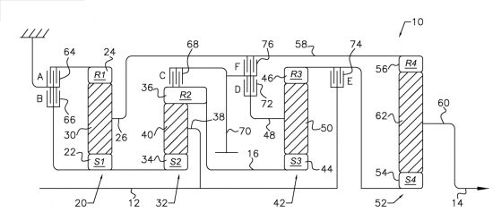
Gear arrangement for a 10 speed automatic from Patent # 8,834,310
Lately there has been a lot of speculation on what the Ford Motor Company has been up to with their 10 speed transmission design. All we know is that there is a joint venture between Ford and GM to develop the next generation 10 speed transmission for next generation RWD trucks and cars. This article pieces together the information available from the invention disclosures from Ford, and makes educated guesses about the actual design. While the author sincerely hopes that these guesses are educated in nature, there is a possibility that the guesses are completely off base. With that disclaimer out of the way, let us look at what facts are at our disposal, and what the Ford 10 speed automatic transmission design is likely to look like when it is sees the light of day. If you are interested, read on.
US Patent number 8,834,310 is one of the many many patents granted to Ford for the design or design elements of a 10 speed automatic transmission. This same basic power flow was first disclosed in US patent number 8,545,362 but clearly it has been refined as the project has progressed. In September 2014, the annual Henry Ford Technology Awards winners were announced. Every year a maximum of ten awards are given out by Ford to recognize and honor technical achievements in the fields of Product Development, Manufacturing, and Research. One of the awards was
“For the design and development of the Next Generation 10-Speed RWD Automatic Transmission Family; advanced automatic transmission technology is critical to meet stringent government fuel economy regulations and customer expectations for increased performance.”
A major auto company like Ford applies for and receives hundreds of patents every year. Looking for what will actually make it to production can be like looking for the proverbial needle in a haystack. The names of the award recipients is an important bit of information that can be used to narrow the search down. But the recipient of such an award is likely to be a prolific inventor who has dozens of disclosed inventions to his or her credit. Thus even with this information, it is not a trivial task to filter out the noise. In a modern automatic transmission, there are dozens of relatively minor but innovative things that are invented as the design is fleshed out. Typically the overall power flow is disclosed in one patent, the finer details are disclosed in subsequent patent applications as the design turns from a doodle to actual drawings that can be manufactured on a mass scale and work reliably over the expected life of a vehicle. An absence of such supporting patent disclosures can mean that the design concept is not being taken much further than a disclosed invention. Another clue is if the patent applications are being filed with international patent offices (EU, China, etc). International patent applications are not cheap, and typically inventions that are headed for production will turn into international patent applications as well to protect the intellectual property in jurisdictions besides NAFTA.
After reading through dozens of issued patents and patent applications, I have concluded that the design concept disclosed in part in Patent is the concept going forward to production. A photochop of the likely cross section put together from the various supporting patents and applications is shown below. I am not sure if I got the width of the fourth planetary gear set and/or the width of clutch pack E correctly, but this should be pretty close to the finished product. The planetary gear set elements and the shafts connecting them are color coded along with the intermediate shaft which is connected to 3 of the shift elements but not to any of the planetary gear sets directly.
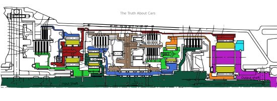
Ford 10 speed transmission cross section design pieced together from various patent disclosures
The salient features of the design are as follows:
- There are a total of 10 forward ratios (of course) and 1 reverse ratio
- There are six forward under drive ratios (i.e. the input turns faster than the output)
- There is a direct drive ratio where the input and the output shafts spin at the same speed
- There are three overdrive ratios (i.e. the output turns spins faster that the input)
- There are 4 simple planetary gear sets, just like the ZF 8HP and the GM 8L transmission families
- There are six shift elements (as compared to 5 for theZF8HP and the GM8L)
- 2 brakes (A and B) that are nested (one shift element is packaged inside the other)
- 4 clutches (B, C, D, and E), two of the clutches (D and F) are nested as well
- For any of the 10 gear ratios, 4 shift elements are closed and two are open. Consequently the frictional losses are likely to be no worse than the 8 speed transmission designs
- The nesting of shift elements means that the overall package size will be pretty similar to the 8 speed transmission designs
- All shifts up and down need one shift element to be opened, and another one to be closed simultaneously. This is identical to how the ZF 8HP and the GM 8L transmissions work. The shift performance should therefore be very good.
So in effect, what this design provides is an additional over drive gear and an additional under drive gear at the cost of an added shift element. The packaging room is similar to the 8 speed designs, and the difference in weight for a given torque capacity should be minimal (within 5 lbs for a given torque capacity with equivalent levels of engineering diligence). The first 2 planetary gear sets and the fourth planetary gear sets are laid out pretty much exactly like the ZF 8HP transmission design. Therefore it is not surprising that first gear is achieved in a manner very similar to the ZF 8HP transmission, i.e. both the brakes are locked which grounds the ring gear, the sun gear, and consequently the planetary carrier of gear set 1. Since The planetary carrier of gear set 1 is connected to the ring gear of gear set 4, the ring gear of gear set 4 is therefore grounded. The engagement of clutch E connects the input shaft to the sun gear of gear set 1. Though not strictly necessary for the operation of first gear, clutch D is also engaged because clutch D needs to be connected for a shift to second gear or to reverse gear. Clutches C and F are the two open shift elements for first gear operation. This sets up an under drive ratio because the carrier of gear set 4 is the output shaft of the transmission, the ring gear is grounded, and the sun gear is connected the input shaft.
The ratio of first gear is therefore
1st =S4+R4S4
This equation is identical to the first gear ratio equation for the GM 8L90 transmission, as well as the ZF 8HP transmission. The GM design has a first gear ratio of 4.55:1, while the ZF design has a first gear ratio of 4.70:1. The second generation ZF 8HP transmission offers first gear ratio of 5.0:1, which is the practical upper limit of the gear ratio such an arrangement can yield. Therefore, I do not expect that the Ford 10R family offers a much shorter ratio than 5.0:1 for the first gear. The 10th gear ratio is expected to be in the 0.6:1 to 0.64:1 range. For comparison, the GM 8L90 has a 0.65:1 ratio for the tallest gear, and the second generation ZF 8HP has a 0.64:1 ratio for the tallest gear. The calculations for all 10 gear ratios are detailed in the companion saturation dive.
Therefore in terms of the overall ratio spread (ratio of the shortest gear to the tallest gear), this transmission design is not going to break new ground, and will likely be similar to the second generation ZF 8HP. I would project an over all ratio spread of around 7.5. So while the ratio spread is similar to the 8 speed designs, the ratio spacing is going to be better because there are 10 steps between the numerically highest and the numerically lowest gear instead of 8.
Additionally this transmission design has many refinements that are not immediately obvious, e.g. the nested layout of the 2 brakes has a measurable advantage over the ZF or the GM friction element layout. The ZF 8HP design and the Ford 10R designs are compared in the figure below
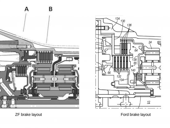
Comparison of the brake arrangements for ZF 8HP and Ford 10R designs
With the ZF design, brake B is disengaged for 8th gear operation. At 3000 rpm transmission output speed (approximately 80 mph), brake B sees a relative speed of 4500 rpm. Therefore even a small amount of drag torque can translate to a substantial power loss and therefore a reduction in the fuel economy. The stationary plates are splined directly to the housing, which is smart because it saves a component but at the cost of added complexity to the transmission housing. But this design decision also has a downside, it limits the ability of transmission fluid to flow through the brake. It is customary to put holes in clutch drums to provide a path for the fluid to flow out of the clutch when it is open. With the transmission housing serving the role of the clutch drum, such holes are not possible because while you want the fluid to be able to leave the shift element, you do not want it to be able to leave the transmission housing (that leads to unhappy customers, warranty, etc). In the ZF 8HP design, the centripetal acceleration due to the angular velocity is slinging the fluid outwards, and that fluid has nowhere to go so it sits inside the brake and causes drag. Even a third of a lb-ft of additional drag torque is a quarter horsepower of power loss, i.e. approximately a quarter of an mpg loss in highway fuel economy.
The Ford 10 speed transmission design on the other hand moves the ground element of the brake to a nested clutch and hub design. Since the 2 brakes are now entirely internal to the transmission, it is now possible to design in the appropriate passages for the fluid to leave. Therefore for the overdrive gears, when brake A (outer brake) has to be open by design, the fluid has a way out of the clutch and therefore the plates spin in air instead of a bath of fluid. This leads to lower drag torques, and could easily account for a 0.1 mpg or more highway fuel economy enhancement over the ZF 8HP design. The original patent disclosure for the power flow had a brake arrangement very similar to the ZF 8HP, while the later invention disclosures go to the nested design. This is an example of the design being refined as the development progresses.
The Daimler 9G-Tronic 9 speed gear box also had 4 simple planetary gear sets and 6 shift elements. But it only accomplishes 9 speeds from the layout as compared to the 10 from the Ford 10R design. At the expense of 1 gear ratio, the Daimler 9G-Tronic design gains a wider ratio spread of 9.16 (first gear ratio of 5.5:1, 9th gear ratio of 0.6:1). On the flip side however 3 of the 6 shift elements are disengaged/open for any given gear, as compared to 2 for the Ford 10R design thereby giving Ford the slight edge in parasitic frictional losses. You win some, you lose some.
ZF CEO has emphatically stated that his company is not going after 10 speed designs for now. Therefore the long list of clients ZF has are presumably happy with the 8HP and the forward evolution of the design. But ZF engineers do have a few disclosures with 10 speed power flows similar to this one (6 shift elements, 4 planetary gear sets, 2 open shift elements in any gear) going back to 2007-9 time frame.
Hyundai and Kia also have invention disclosures with a power flow that is in effect very similar. So it is possible that 10 speed transmissions are also on the horizon for the luxury offerings from the 2 brands.
General Motors has officially partnered up with Ford to use this design in the future. Ford appears to be leading this design effort, and in return GM appears to be leading the design effort for the 9 speed FWD transmissions. Though the GM 8L family is an excellent design in its own right, but perhaps the economies of scale inherent in a partnership are attractive enough for them to adopt this design after a relatively short time with the 8L family.
The rumor has it the first prototypes were installed in test vehicles late last year, and the controller software development is in full swing right now. Unless the software team is working extra fast, 2015 CY is unlikely. Likewise for the production tooling, I doubt that it is possible to tool up this transmission within 18 months of first vehicles level prototypes. While it is possible that this transmission shows up for 2016 model year in late 2015, it seems more likely that it actually does not show up till the middle of 2016 for 2017 model year vehicles.
This is a good solid design, kudos to the design engineers at Ford for making this happen. A project of this kind is not a trivial undertaking, and I am sure there is a tale of blood, sweat, and tears behind this design. While the mechanical design seems fairly complete, the Tresmonos of the world are probably slaving away to get the tooling all set up as this article is run. At the same time the code monkeys are likely working just as hard on the software to make sure that this transmission shifts like the best. It is safe to say that there are more missed anniversaries and birthdays ahead for a large team at Ford and GM.
Forward progress seldom comes without an effort. This is forward progress.
The first commentator to say CVTs are better shall find coal in his or her stockings. A CVT design with this much torque capacity is yet to be seen. Physics, it can be a pesky thing.
For all 10 gear ratios, and details of the operation of the transmission, please refer to the saturation dive.
The author would like to stress again that all information presented in this article is from publicly available sources, mostly the USPTO website. Internet, it can be a wonderful source of information.
More by Timur Apakidze


Comments
Join the conversation
I just have one question which is, in 2027 when I've racked up 175K miles and that ten speed thingamajig craps out, how many of my grandchildren will I need to sell into bondage to pay for a rebuild?
Sad that the 10R60 isn't surviving in the Ford Explorer. The F clutch burnt in mine at 16,000 miles and the transmission had to be replaced due to no parts available. A similar story of woe can be found across the internet. Poor or non-existent testing? I'm sure a class action suit is on the horizon. My vehicle was in the shop for 2 months.