


Saturation Dive: Ford 10 Speed Transmission Power Flow
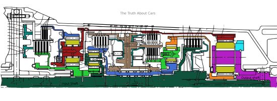
Ford 10 speed transmission cross section design pieced together from various patent disclosures
If a transmission has 5 clutches and for the realization of a gear ratio 3 out of the 5 clutches have to be engaged, there are a total of 10 possible combinations. The ZF 8HP and GM 8L transmission families have 5 clutches of which 3 are engaged for any gear state, but only have 9 out of these 10 states are present and accounted for (8 forward gear ratios along with 1 reverse gear ratio). The 10th combination leads to a situation where the transmission would want to turn in forward and reverse direction at the same time, i.e. the transmission would lock up the output shaft and potentially self destruct. The Ford 10R transmission design has 6 clutches and 4 are engaged for any given gear ratio. This gives us 6C4 or 15 possible combinations, 11 of which are used to yield 10 forward gear ratios and 1 reverse gear ratio. The 4 other combinations do not yield a functional transmission gear state or put the transmission in Neutral.
In the last article on the Ford 10 speed transmission we looked at some of the design details of the Ford 10 speed RWD automatic transmission without going into the details of the actual power flow for the various gears. In this article, a detailed analysis of the power flow is presented along with the gear ratio calculations and shifting operation of the transmission. Just like the last article on the subject, the information is based on invention disclosures by Ford. The most relevant patent for the purpose of understanding the power flow is US Patent .
The casual reader is advised to go through the basics of planetary gear sets from the earlier saturation dive articles before wading into this detailed analysis. The simplified representation of the 10R design or the “stick diagram” of the Ford 10R design is presented below
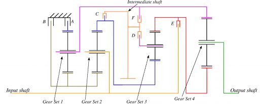
10R80 stick diagram
The output shaft of the torque converter is the input shaft to the transmission. The output shaft (Gear set 4 planetary carrier) is connected to the rear wheels through a prop shaft. All 4 planetary gear sets are “simple” planetary gear sets, for the definition of a simple planetary gear set please refer to the ZF 9HP transmission saturation dive. The 4 gear sets have the following rigid links
- Planetary carrier of gear set 1 is rigidly connected to the ring gear of gear set 4
- Ring gear of gear set 2 is rigidly connected to the sun gear of gear set 3
- Planetary carrier of gear set 2 is connected to the input shaft
- Ring gear of gear set 3 is rigidly connected to the sun gear of gear set 4
- Sun gears of gear sets 1 and 2 are rigidly connected.
The function of the shift elements is as follows
- Activation of brake A grounds the ring gear of gear set 1
- Actuation of brake B grounds the sun gears of gear sets 1 and 2
- Engagement of clutch C causes the ring gear of gear set 2 and the intermediate shaft to rotate at the same speed
- Engagement of clutch D causes the planetary carrier of gear set 3 and the intermediate shaft to rotate at the same speed
- Engagement of clutch E connects the sun gear of gear set 3 and the ring gear of gear set 4 to the input shaft
- Engagement of clutch F causes the ring gear of gear set 4 and the planetary carrier of gear set 1 to rotate at the same speed.
The astute reader will note that there are several similarities between this design and the ZF 8HP design in terms of gear layout as well as brake A and B layout. Of course there is one additional shift element (a rotating clutch), and there is an intermediate shaft that is not directly connected to any gear set element unlike the ZF 8HP design. The 5 rigid links between the gear set elements are in fact exactly the same as the ZF 8HP design. Please refer to the ZF 8HP transmission saturation dive for the ZF 8HP stick diagram and CAD renders. A CAD render of the Ford 10R may therefore appear very similar to the ZF 8HP CAD render to the casual observer.
For the 4 simple planetary gear sets, the gear tooth counts are estimated to be
- Gear set 1: Sun gear S1 = 45 and Ring gear R1 = 99
- Gear set 2: Sun gear S2 = 51 and Ring gear R2 = 89
- Gear set 3: Sun gear S4 = 63 and Ring gear R3 = 101
- Gear set 4: Sun gear S4 = 23 and Ring gear R4 = 85
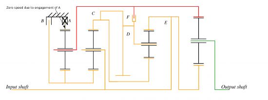
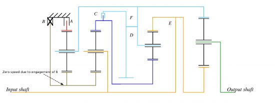
First gear is achieved by engagement of brakes A and B, along with actuation of clutches D and E. A simultaneous actuation of brakes A and B causes the sun gear and the ring gear of gear set 1 to be grounded, thereby causing the planetary carrier of gear set 1 to be grounded. By the virtue of a rigid link, the ring gear of gear set 4 is also grounded. Clutch E connects the input shaft to the sun gear of gear set 4, while the planetary carrier is the output. The figure below explains the speed states of the various members. The power flows through Clutch E to the sun gear of gear set 4, the ring gear of gear set 4 provides the reaction torque which flows back to brakes A and B. Clutch D need not be engaged for the first gear to work, but it is engaged because it is required for a shift to 2nd gear or to reverse gear. Clutch C is open and sees a relatively small amount of relative speed, while clutch F is open and sees a large amount of speed difference (slightly higher than input speed).
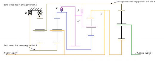
10R80 1st gear kinematic state
In the figure above, all elements that are color coded orange spin at the input speed, and the beige color denotes 0 speed. The blue colored elements spin faster than the input and the purple colored elements spin faster than the input but slower than the blue elements. This sets up an under-driven gear ratio of
(1)1st =S4+R4S4
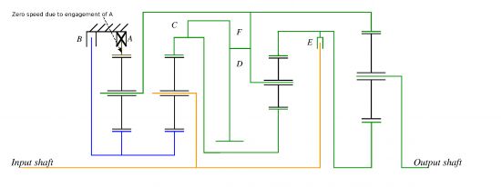
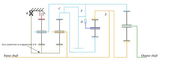
= 4.696 Second gearA shift to second gear is accomplished by releasing clutch E and engaging clutch C, while shift elements A, B, and D stay engaged. This causes gear set 2 to act as an overdrive because the sun gear is grounded, the planetary carrier is rigidly connected to the input shaft, and the ring gear is the output element. Since clutch D is closed, the planetary carrier and the sun gear of gear set 3 are forced to turn at the same speed as the ring gear of gear set 2. Therefore, gear set 3 spins as a unit, i.e. all 3 members are turning at the same speed. The power flows from the planetary carrier of gear set 2 to the ring gear of gear set 2 to the sun gear of gear set 4 to the output shaft. The reaction torque is provided by brakes A and B through the ring gear of gear set 4
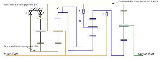
10R80 2nd gear kinematic state
In the figure above, the orange colored elements spin at the input input speed, while blue colored elements spin faster than the input. The beige colored elements are stationary. Clutch E is open and sees a low speed difference, while clutch F is open and sees high speed difference at approximately 1.5 times the input speed. The overall ratio between the input and the output is a net under-drive with the following ratio
(2)2nd =(S4+R4)R2S4(R2+S2)
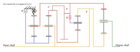
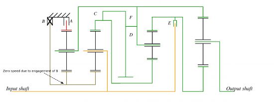
= 2.985 Third gearThe shift to 3rd gear is realized by disengagement of brake B and engagement of clutch E. A simultaneous engagement of clutches C, D, and E causes all 3 elements of gear sets 2 and 3 to spin at the same speed as the input. Since brake A is still engaged, the planetary carrier of gear set 1 and therefore the ring gear of gear set 4 is under driven with respect to the input. Meanwhile the sun gear of gear set 4 spins at the input speed. Brake B sees a high speed difference across it (since the inner plates of the clutch are spin at input speed), while clutch F has a relatively low relative speed.
10R80 3rd gear kinematic state
In the figure above, the orange colored elements rotate at input speed, beige colored elements are stationary, and the red colored elements are under-driven. In this state, gear set 4 acts as a mixer module with an under driven ring gear and a sun gear that rotates at input speed. Since the speed of the carrier is always a weighted mean of the speeds of the sun and the ring gear, the ratio is as follows
(3)3rd =(S1+R1)(S4+R4)R1S4+S1(S4+R4)
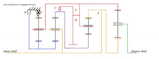
= 2.179 Fourth gearFourth gear is achieved by opening clutch E, and closing clutch F. The simultaneous actuation of clutches C, D, and F causes the following
- Clutch C and D closed implies the sun gear and the ring gear of gear set 3 rotate together, which means the ring gear of gear set 3 and consequently the sun gear of gear set 4 also turn as the same speed as ring gear of gear set 2.
- In addition to the constraint above, closing clutch F means that the ring gear of gear set 4 also rotates at the same speed as the ring gear of gear set 2
- Therefore gear set 3 and gear set 4 spin as a unit at the output shaft speed
10R80 4th gear kinematic state
In the diagram above, all elements that are color coded green spin at the same speed as the output, while the orange color denotes the input shaft. The blue colored elements spin at a speed that is faster than the input. Therefore the gear ratio only depends on the gear ratios of gear sets 1 and 2. The exact formula for the gear ratio is
(4)4th =S1(S2+R2)+R1S2S1(S2+R2)
= 1.801 Fifth gearThe shift to fifth gear is realized by opening clutch D and engaging clutch E. This change in clutch actuation does not alter the kinematic behavior of the first 2 gear sets. Therefore the ring gear, the sun gear, and the planetary carrier are still rotating 1.801 times slower than the input. The speed difference across the open brake B is identical to fourth gear as well. The carrier of gear set 3 now rotates slower than the input, and gear set 4 is acts as a mixer module.
10R80 5th gear kinematic state
The orange colored elements rotate at input speed, the red colored elements rotate 1.801 times slower than input speed, the blue colored elements turn faster than input, and the purple colored element is slower than input. Therefore the gear ratio is defined by the gear ratios of gear sets 1, 2, and 4. Since the ring gear of gear set 1 rotates at 1.801 times slower than input, and the sun gear is connected to the input, the overall ratio is an under drive
(5)5th =(S1(S2+R2)+R1S2)(S4+R4)S1(S2+R2)(S4+R4)+R1S2S4
= 1.539 Sixth gearSixth gear is achieved by releasing clutch C and engaging clutch D. The resulting kinematic arrangement forces the following speed relationships
- The sun gears of gear set 1 and 2 spin at 1.291 times the input shaft speed (color coded blue in the figure below)
- The ring gear of gear set 4, the planetary carriers for gear sets 1 and 3 all rotate 1.397 times slower than the input shaft (color coded red in the figure below)
- The ring gear of gear set 2 and the sun gear of gear set 3 rotate 3.841 times slower than the input shaft (color coded purple in the figure below)
10R80 6th gear kinematic state
Therefore gear set 4 still acts as a mixer module, and since the ring gear speed is 1.397 times lower than the input shaft speed, the overall ratio is an under drive. The formula below shows that tooth count of all 4 gear sets result in the over all gear ratio.
(6)6th =(S4+R4)(S1R2(S3+R3) + S1S2S3 + R1S2S3)(S4+R4)((S1R2(S3+R3) + S1S2S3)) + R1S2S3S4
= 1.288This gear ratio calculation was a real bear, it took me 4 of my most productive hours to finally arrive at the pithy equation above. But as we have seen before, the numerically small under drives of these modern automatic transmissions are generally quite complicated in operation.
Seventh gearThe shift to seventh gear is accomplished by releasing brake A and engaging clutch C. This means all members of all 4 gear sets turn at the same speed as the input. The ratio is therefore
(7)7th =11
= 1.000Simplicity is nice, once in a while. The 3 remaining gear ratios are all overdrives.
Eighth gearThe shift to Eighth gear is realized by releasing clutch C and engaging brake B. Since the sun gear of gear set 2 is now grounded, and the planetary carrier is connected to the input shaft, therefore the ring gear of gear set 2 rotates faster than the input shaft. Gear set 3 acts as a mixer module, since the ring gear is tied to the input shaft through clutch E, and the sun gear is tied to the over driven ring gear of gear set 2. The planetary carrier of gear set 3, rotates faster than the input, but not as fast as the ring gear of gear set 2.
10R80 Eighth gear kinematic state
The orange colored elements rotate at the speed of the input shaft, the dark blue elements rotate at 1.57 times the input speed. The light blue colored elements spin at 1.22 times the input speed. Therefore gear set 4 acts as a mixer module since the ring gear rotates at 1.22 times the input speed and the sun gear rotates at the input speed with a ratio of
(8)8th =(S4+R4)(S3+R3)R2(S4+R4)(S3+R3)R2 + S2S3R4
= 0.852The ring gear of gear set 1 rotates at 1.775 times the input speed. Therefore the relative speed difference across brake A is 1.775 times the engine speed assuming that the torque converter is locked up.
Ninth gearThe shift up to the Ninth gear ratio is achieved by closing clutch C and opening clutch D. This simplifies the kinematic state of the transmission and takes gear set 3 out of the equation. Now the ring gears of gear sets 2 and 4 are connected, and are over-driven with respect to the input shaft. The light blue colored elements in the figure below rotate at 1.57 times the input speed instead of 1.22 times the input speed in Eighth gear.
10R80 9th gear kinematic state
In a manner very similar to Eighth gear operation, gear set 4 is a mixer module with a ring gear rotational speed 1.57 times faster than the input while the sun gear rotates is coupled to the input through clutch E. This sets up an overdrive ratio of
(9)9th =(S4+R4)R2(S4+R4)R2 + S2R4
= 0.689 Tenth gearThe shift to the the 10th and final forward gear is achieved by releasing clutch E and engaging clutch D. This kinematic state is a pretty simple one, gear sets 3 and 4 now spin at at the same speed as the output shaft, while gear set 2 acts as an overdrive.
10R80 10th gear kinematic state
The sun gear of gear set 2 is grounded, the planetary carrier is the transmission input and the ring gear is effectively the transmission output. This sets up a straightforward overdrive ratio of
(10)10th =R2S2+R2
= 0.636The relative speed across clutch E is 0.36 times the input speed, while the relative speed across brake A is 2.28 times the input speed. This is a very high efficiency state with a locked torque converter, much like the top gear operation of the GM 8L family or the ZF 8HP family.
Reverse gearReverse is achieved by engaging shift elements A, B, D , and F. Simultaneous engagement of these 4 shift elements locks the carrier of gear set 3 to ground, turning it into a reversing unit. For reverse gear operation, gear set 2 acts as an overdrive, gear set 3 acts as an under drive and the reversing gear set, while gear set 4 acts as an under drive.
(R)Rev =-R2R3(S4+R4)S3S4(S2+R2)
= -4.786The first gear ratio and the reverse gear ratio are numerically quite close to each other, which is not possible with the power flow of the ZF 8HP. The ZF 8HP is yet to show up in a RAM 2500/3500 application, and I suspect that for heavy duty user cases, e.g. snow plow operation, numerical parity between first and reverse gear ratios is important.
The gear ratio numbers presented here are estimates based on the patent filings, the actual gear ratios when the 10R transmission family sees the light of day might very well be slightly different. As noted in the last article, this transmission is unlikely to meet the gear ratio spread of the 9G-Tronic, but the spacing between the gears is pretty much spot on. In my humble opinion, the ground the Ford design gives up to the 9G-Tronic in gear ratio spread, it will probably make up in efficiency because of 1 less open shift element in any given gear.
The genius of this design is the use of an intermediate shaft which is connected to 3 of the 6 shift elements. This intermediate shaft allows for 10 well spaced ratios between the highest and lowest gears, and also simplifies the hydraulic system of the transmission because hydraulic power for half the shift elements goes through one rotating shaft. This kind of design is far too complex to be totally invented by a human because there are simply too many permutations and combinations to consider when evaluating a power flow. Therefore candidate designs are typically brute forced by computers and subsequently short listed and refined by carbon based life forms. The use of such an intermediate shaft that is not directly connected to any of the planetary gear elements is truly unique, and leads me to believe that the transmission synthesis software used at Ford is a step or two ahead of the transmission synthesis software used by the other big boys of transmission design. There are patent disclosures out there from ZF with 4 gear sets and 6 clutches that do yield 10 forward ratios and 1 reverse, but the ratio spacing is rather less than optimal. In US Patent ZF has disclosed a power flow which has ten forward ratios, but 5th and 6th gears ratios are practically equal to each other, and so are the 8th and 9th gear ratios. Additionally there are 3 open shift elements for any given gear ratio, thereby the transmission concept disclosed in this patent would have a lower efficiency than the Ford design.
That is all I have to say about that.
More by Timur Apakidze


Comments
Join the conversation
When a multi gear downshift is required do these things have to cycle through all the in between power paths or can they jump from 8 to 5? Is the quickest way down being to drop torque and cycle down through a large number of changes at no torque transferred why some newer vehicles have such a fierce case if "who, me" when poked while already moving?
Thank you for such an elegant written article! I really enjoy your writing style! Please continue enlightening us minions!