


Exclusive: TTAC Takes Apart Both Toyota Gas Pedals
Update: To see all of TTAC’s related articles on the subject of Toyota gas pedals, go here:
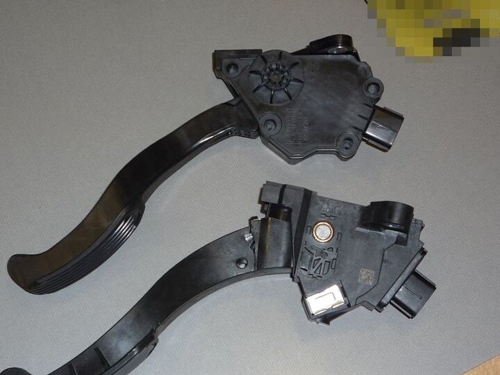
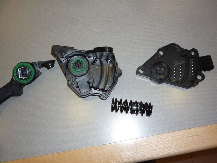
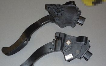
In yesterday’s post , we offered a bounty for anyone to open up both the CTS (bottom) and Denso (top) Toyota gas pedal assemblies. No one took us up, and no one anywhere else has done it, so we took it upon ourselves . Here they are, both e-pedal assemblies taken apart and examined, in our quest to understand if and what the significant differences are, and how Toyota’s possible “shim” fix would work. On initial observation, it appears that the CTS may be perceived as being the more solidly engineered/built unit, in that the pedal pivots on a traditional and solid steel axle whose bearings are brass or bronze sleeves. The Denso’s whole pivot and bearing surfaces are relatively flimsy-feeling plastic. But that can be deceptive, and we’re not qualified to judge properly if it is indeed inferior or superior. So the question that goes beyond the analysis of these e-pedals is this: are these units really the full source of the problem, or are they scape goats for an electronics and/or software glitch? Pictures and tear down examination and analysis follows:
Update It’s clear to me now that the CTS unit I took apart already had the side cover plates (sheet metal) removed before I examined it. One can see where they fit, and are obviously intended to protect the exposed axle pivot and bushing seen above and below:
(Update Also see our follow-up stories on Toyota’s fix and our replication of the fix and its results)
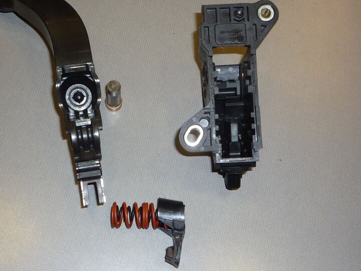
Lets take a close look at the CTS unit:
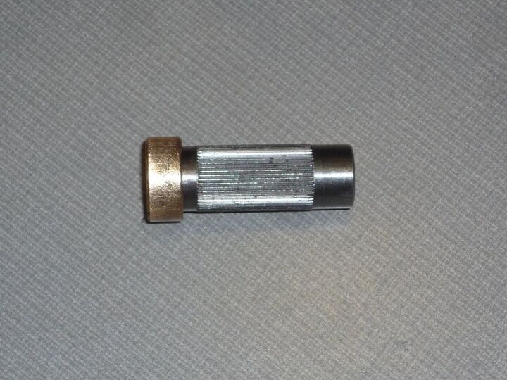
We drove out the pivot pin with a C-clamp and screwdriver. It’s a very traditional design, like millions of plain-bearing (non roller-ball bearing) non-lubricated devices used in a huge variety of devices for decades, if not even centuries. The softer brass or bronze acts as relatively low-friction bearing. With the substantial pressure from the springs, it seems relatively unlikely that this would lock up, but that seems to be the concern. It’s possible that there is a greater potential for binding due to the tighter tolerances in the axle/sleeve assembly. A close up of the axle and bearing:
A big question for us was if there are dual springs, in the case one fails. Here is the CTS unit apart. Note that the pointed metallic part on the bottom of the pivot is the magnet that passes between the sensors in the case of the unit, which is how the sensor sends the throttle position signal to the engine controller.
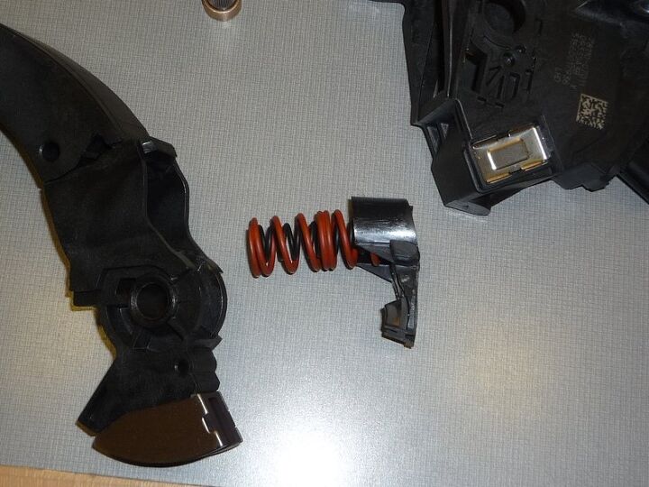
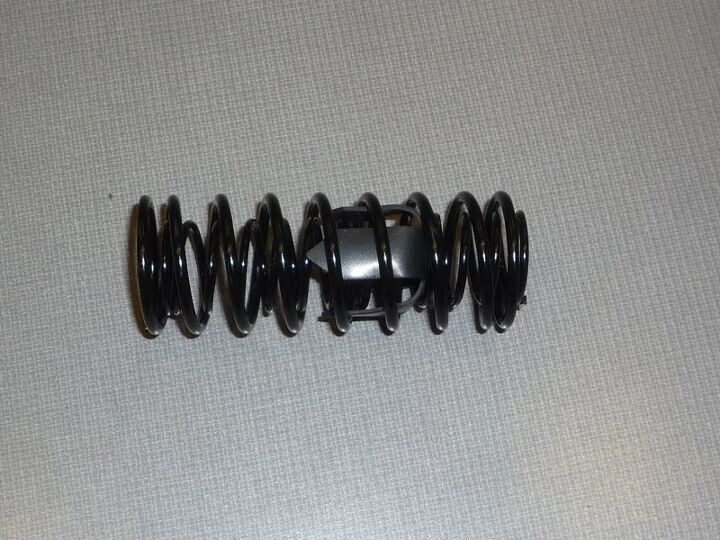
The outer red spring surrounds the inner black coil spring. It seems that the possible “shim fix” that Toyota is considering would be a spacer on the bottom of this spring assembly, which would increase the pressure on it and presumably reduce the likelihood of the pedal sticking. I’m not an expert on springs, but the spring is already pre-loaded (compressed) to some degree when it is assembled, and unless these are variable rate springs, I wonder whether that would actually increase the working resistance of the spring unit. Since I had no problem taking the pedal/pivot unit apart which also houses the spring unit, and reassembling it as well, it would appear that if that route is taken, it should be easily done in a few minutes at the dealership.
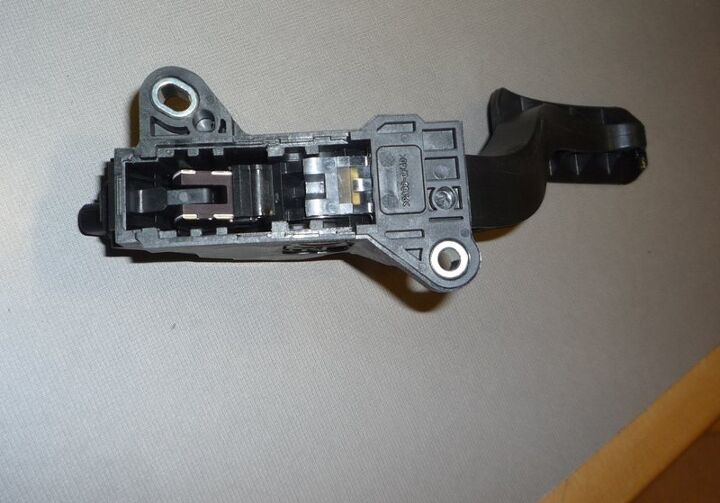
To understand that part more clearly, here is a shot of the CTS unit assembled, with the main cover off, showing the pivot arm with the magnet and how it passes past the sensors ( Autoblog has a video explaining how the CTS sensor works, but no teardown):
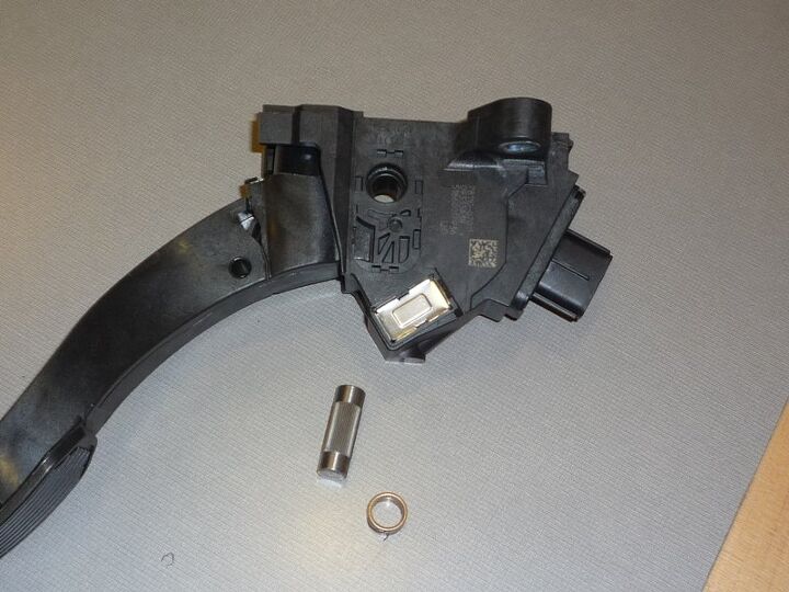
Lets examine the Japanese Denso unit (below, which comes apart by removing the side cover held on by five screws. It is already apparent from the outside that there is no axle pivot that runs through this unit.
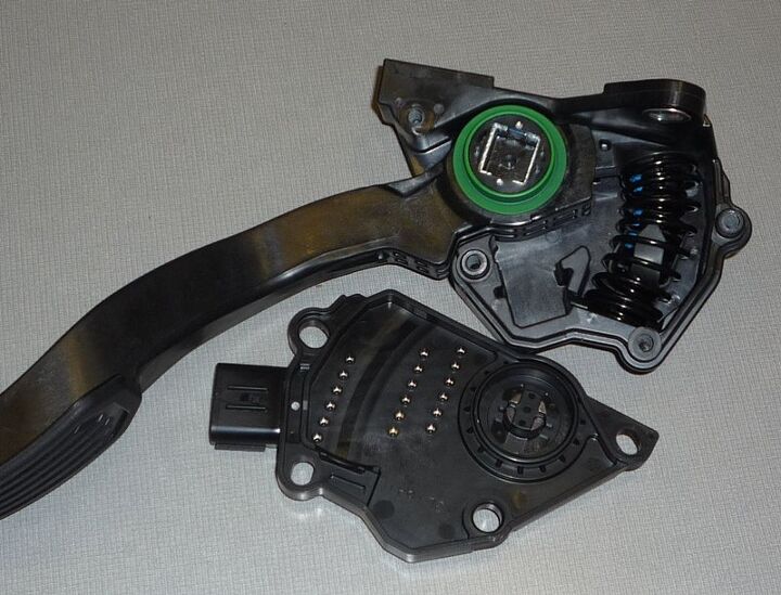
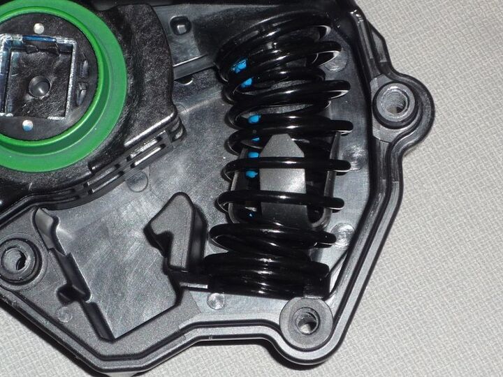
The Denso is a dramatically differently designed unit. The pivoting unit (green) is a plastic “bearing” that just sits inside the two outer units. One can see what it bears against in the side cover. The magnet is the square unit in the middle of the green pivot, and the sensor appears to be the round unit inside the side cover. The numerous small bright metal protrusions on the side cover are not identified. I thought they were the sensors, but nothing runs over/past them. Here is a closer look at the spring assembly still installed and the plastic pivot “bearing” surface:
Here’s another view of the Denso unit:
The Denso spring unit, also a double coil unit, has a protective “sleeve” over the inner spring to reduce binding between them, since the Denso unit’s spring is in a substantially curved position inside the housing. The CTS does not have this feature, but it appears that its spring is less curved when installed.:
Subjective impressions of taking these two units apart are the opposite of what one typically would assume. The Denso unit feels “cheaper” in that the whole pivot bearing area is all plastic, and feels relatively more flimsy (that doesn’t necessarily mean it actually is). The CTS unit relies on very traditional steel and brass sleeve bearing that took some effort to take apart. The CTS pedal has no play or wiggle when assembled.
The big question is why Toyota completely redesigned the CTS unit from the older Denso unit. Perhaps they were actually trying to design a sturdier assembly because the Denso unit was in question. Perhaps the Denso unit is actually inferior in certain ways, but Toyota didn’t want to pay for new tooling to bring the Denso unit up to the newer CTS design? Source have told me that the Denso unit is likely to be recalled shortly, and the LA Times is reporting that there are known claims of pedal issues with the Japanese Denso unit.
From our perspective, it seems possible but rather highly unlikely that condensation is somehow causing the very solid CTS bearing pivot to lock up, given the spring tension and the units solidity. CTS claims it has only experienced a very limited degree of stiction at or near the idle point on a very few examples.
A key question is which unit was designed first. The CTS unit was used in Avalons since ’05 MY. Apparently Denso units have been in use before that. The question being: why did Toyota design two such fundamentally different units, and is the latter one designed to address any deficiencies of the older one?
Both units are surprisingly simple and obviously cheap, yet they feel robust when assembled. I believe Toyota has stated that the unit cost is $15 per pedal assembly. The retail price is about $120.
The overriding question is if these pedals are really the predominant or sole cause in any true (non-floor-mat caused) unintended acceleration, or whether electronics are the real 800 lb gremlin in this whole affair. Toyota has not acknowledged that…yet.

More by Paul Niedermeyer


Comments
Join the conversation
Obviously this is not your Daddy's simple stuck mechanical throttle linkage problem which I'm old enough to remember and have experianced. But, this certainly does appear to be a case of classic failure analysis where a series of chain of events is in place, and a break in the link would have prevented these tragedies. This is somewhat in response to gsally's post, because my initial thought was a software/firmware infinite loop. But, is the infinite loop caused by the sensor return it is reading, and doing exactly what it is suppose to do? Making it a mechanical failure of unknown and difficult to duplicate origin. Throw in the lack of foresight to see the potential for this catastrophic failure, with no failsafe mechanism to simply kill the vehicle easily, and this is the result. Hopefully they will find, reveal the truth, and it will be interesting to see who's conjecture is close.
GREAT pictures of the dissassembled pedal TTAC. Based upon your pictures, and the ABC TV and SIU professor video, and my plastic insert molding background, I will tell you what I think, my guess, is the root cause of the DENSO sudden acceleration problem. Problem Definition; Toyota cars suddenly accelerate on their own. 1. The professeor at SIU by shorting out 2 "wires" can make the Toyota car accelerate full blast. I think the professor shorted out the wires in the wire harness coming of this pedal. He just knew if you shorted 2 of the wires that the car would take off full speed. The SIU professor said if you short out the 2 sensors in the pedal the car would take off. It is my opinion that this insert molded housing is somehow shorting out. That is why the CTS design does not use a spring sandwhiched inbetween 2 plastic parts as a friction device. FYI the pedal would have 2 sensors to see the postion of the pedal. If one sensor failed, the idiot light would go on ... on your dash board, and the car would go into a limp home mode.... or something like that. My guess is that there are 6 pin outs on the connector, 3 belog to one sensor , 3 belong to the other sensor. Based upon the 3 rows of 6 stamping support pins, there appears to be 6 "individual" stampings that have insert molded in this housing. It is these stampings that somehow short out. 2. The root cause is electricity is flowing from one of the stamping-support-holes in the cover, to another stamping support hole in the cover. Let me explain stamping support holes first. Several of you have commented on the 3 rows of 6 small holes (i guess the holes are .062 inches in diameter, and 1 mm deep). Someone correctly identified the holes as stamping support pins. Typically the stamping is squezed inbetween a pair of stamping support pins. On the inside of this housing, you can see the shiny pure - tin (probably not tin-lead) plating on the copper stamping thur the holes left by the stamping support pins. Normally there are matching holes on the other side of the part. When plastic is squirted into the mold these stamping support pins, along with stamping support pins on the other side, or a sacrificial insert, or a premold, squeeze and hold the stamping in the middle of the plastic. My guess is, that Somehow along this assemlby 2 of the 6 stamping traces short out amougst each other, causing instant excelleration in toyota cars Here are possible ways how electricity can flow from one stamping circuit to another, even if all of these have to happen together. Keep in mind the stamping is probably .032 inches thick, 1.5 mm wide, CDA210 copper alloy, with tin plating. These "circuits" are probably spaced about 1.5 mm apart, inside the platic. It is possible that during molding some of these traces move closer to each other so the gap is say 1.0 mm ... or less. 1. The spring wears and leaves metallic dust in the housing. the spring is metal, the dust builds up in two holes (holes left by stamping support pins) that are touching the spring, and short circuit occurs between 2 stamping traces. The dust from the plastic might contain carbon-black as a coloring agent which could conduct electicity. 2. During insert molding the plating flows off the stamping and makes a conductive path to the surface of the platic part. The resin the housing is made from wether it is pbt, or nylon (PA=polyamide-nylon), melt at 500 degrees F, and tin plating reflows at say 300F. With no lead in tin plating it melts at an even lower temp. The plating refow could cause a short. the plating could just reflow around a stamping support pin. 3. Each molded housing is most likely electrically tested with both ,a high-potential test, and a continuity test. If there is a short cicuit caused by (for example) say a wisker tin plating that was buried in the part, the hipot test would vaporize this "short cirucit", but a carbon trail or someting remains in the plastic where this short was. If you test the part a 2nd time it would pass the hipot test and the housing could be deemed good. Coupled with other factors this could contribute to a short circuit. That is the remenants of what caused the short, but was burnt away, could contribute to a short later, even if it passed a subsequent hipot and continuity test. 4. If retractable stamping support pins are used on the outside of the housing (that is why you can not see the tin plating of the stamping on the outside) the knit line of these pins does not make a water tight seal. That is retractable stamping support pins leak, they do not make a hermetic sea. That is, the method used so as not to have stamping support pins visible on the outside of the housing, DOES leave a possible path for water to penetrate to the stamping. Perhaps moisture could collect on the outside of the housing and short out between these knit lines. It is difficult to explain all the ways this pedal assembly, with insert molded housing, with stamping support pins, can short in a few lines, in a half hour of quick typing... I'll bet a virtual beer that i am corret on my guess Thanks for this web site to allow me my opinion. A Shifty 1