


Saturation Dive: Manual Transmission Gear Design
In the automatic transmission racket, there have been new layouts and power flows galore lately. Your humble author has done a few articles detailing some of the more common designs in the North American market place, with the notable exception of the Aisin design. The design of a RWD manual transmission, on the other hand, is conceptually largely unchanged from the earliest 3 and 4 speed designs like the venerable M22 Rock crusher.This is not to say that RWD manual transmissions have not changed over the decades. The number of gears and torque capacities has increased, shift efforts have gone down, refinement has increased, which are all good things. This article provides some insights into the gear design and sizing for some of the more recent manual transmissions.
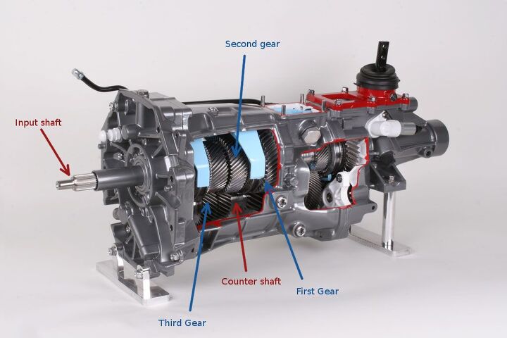
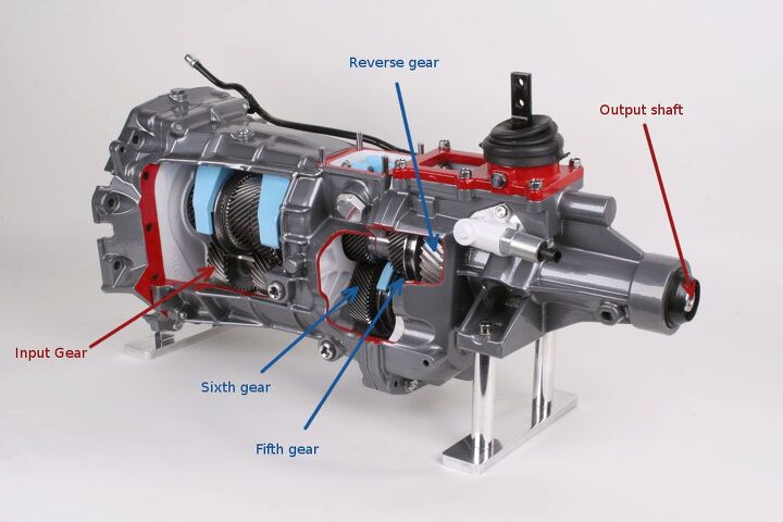
A RWD manual transmission consists of an input shaft, a counter shaft, and an output shaft (also referred to as the main shaft). The input shaft is connected to the engine through a friction clutch, while the output shaft is connected to the drive wheels through a final drive gear and a differential. The counter shaft is rigidly connected to the input shaft through the input gear set. It spins opposite to the input shaft in all gears, and counter to the output shaft in all forward gears. The input shaft and the output shaft are almost always coaxial. For heavier duty applications, there can be more than one counter shaft to increase load capacity. The basic components and operation of a RWD manual transmission are explained in great detail below.
For the uninitiated, this video explains manual transmission operation very well. It is 24 minutes long, and many of the B&B will need to pause this video a few times, but any time you spend understanding this video is time well spent. With that out of the way, let us get to the gear design, specifically the first gear.
The torque capacity of a gear set is determined by the following design parameters.
- Center distance between the main shaft and counter shaft (more is better for torque capacity)
- Face width of the gears (more is better for torque capacity)
- Helical angle of the gears (Does not make as much difference as 1 and 2, but generally speaking less angle is somewhat better)
- Gear ratio (Numerically lower is better for torque capacity, which is one of the reasons why the Corvette ZR1 has a 2.29 first gear ratio)
- The pressure angle of gear set (Complicated, it balances the contact life of the gear with the tooth root life)
The center distance of the TR6060 is 85 millimeters. Face width is 30 millimeters for the first gear (up from approximately 26 millimeters in the T56). The helix angle appears to be around 25 degrees, but as stated earlier it does not have a big impact on the torque capacity so the exact value is not as important. The TR6060 is offered in several first gear ratios, for the purpose of this article, we will focus on the Corvette Z51 first gear ratio, which is 2.97:1. The gear ratio is achieved in two steps. The first step is ratio between the input shaft gear and the counter shaft gear (38 teeth driven and 29 teeth driver), the second step is the first gear set (43 teeth driven, 19 teeth driver) for an overall gear ratio of (43*38)/(29*19) or 2.9655. One thing to note is that of the 4 gears, the number of teeth on 3 of them are prime numbers (43, 29, and 19) while the fourth one (38) is a multiple of a relatively large prime number. This is done to ensure that every teeth on a given gear meshes with every other teeth of mating gear the same number of times to maximize the operating life. With even-number-tooth gears, the same teeth tend to come into contact again and again, exacerbating potential issues.
Some of the essential gear nomenclature is shown in the figure below
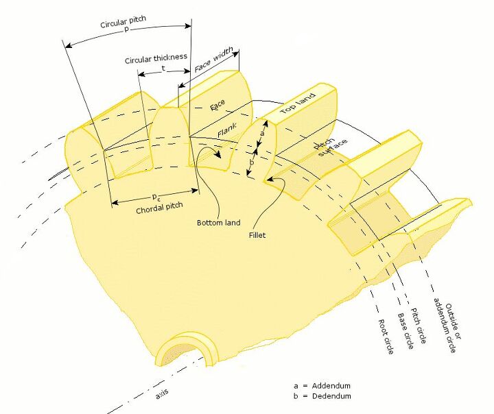
There are two failure modes for a gear with no quality issues. The flank can exhibit surface scuffing and/or pitting if the contact pressure is too high or the lubrication is inadequate. Alternately, the tooth can break off at the root fillet due to excessive bending stress. Any given tooth root is essentially a cantilever under bending. There are several different methods to size gears: there are excellent AGMA standards, many different commercial software packages specifically meant to design gears, and Finite Element Analysis. Finite Element Analysis (or FEA) breaks down the geometry into several “elements” of a finite but small size. The underlying physics is solved for in each domain to assemble a stiffness matrix (and for dynamic problems a mass matrix as well), and the stiffness matrix is then solved for stresses in the part. We are going to use FEA to analyze these gears because in the humble opinion of the author, FEA is the most accurate of all design methods for gears provided it is done right.
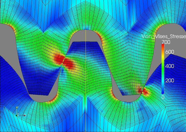
For the rated 600 lb-ft torque capacity, the first gear set has to carry approximately 780 lb-ft. If the 43T/19T gear pair was a spur gear with “standard” gear design parameters with a 20 degree pressure angle, the stress contours for the gear design are shown below. The stress numbers are in MegaPascals or Newtons of force per square millimeter of area.
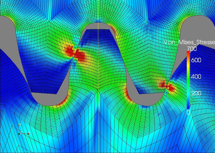
The surface contact stress is well within the limits of what is generally accepted for gear steels, while the tooth root bending numbers are a tad high. You, the driver, would be limited to about 150 miles of driving at rated torque of 600 lb-ft in first gear, which is actually quite a bit of useful life. (Autocrossers beware! — JB) 700 MPa or 100 ksi is widely accepted as the cyclical endurance limit of good quality gear steels with proper heat treatment. The root fillet of the drive gear tooth is where we see the highest tensile stress of approximately 700 MPa or 100 ksi. But since the torque going through this gear set is mostly in 1 direction (except for engine braking or missed shifts into 1), the 100 ksi limit is a little conservative because for situations where tensile and compressive loads are not equal, there is approximately a 20% safety margin at the rated torque level. This correction in life is known as the Goodman correction, and it increases the life by a factor of 2 to 2.5. Therefore for this simplified spur gear set, the design life increases to approximately 400 miles at the rated torque of 600 lb-ft.
A simple way to improve the performance of this gear set is to make the 19T drive gear circular tooth thickness a little higher, at the expense of the thickness of the driven gear tooth, to “balance” the stresses in the two gears. This is also a good idea because the smaller drive gear sees more stress cycles per tooth than the larger drive gear anyway. The gear design shown above is also not practical because there is no lash between the gears, which is generally a bad idea for manufacturability of the parts among other things. The results for a modified gear are shown below
It may be hard to tell from the stress contour, but the changes in the circular tooth thickness reduced the fillet root bending stresses by approximately 5 percent, increasing the margin in the design to approximately 25%, which gets the design life close to 500 miles in first gear at the rated engine torque of 600 lb-ft.
Now obviously the gears in a TR6060 are not spur gears, they are helical gears. If I had a large computer to run analyze the helical gear geometry, it would not be a big deal to analyze the gear geometry with the helical angle thrown in, but as it stands I have a laptop that does everything well except for number crunching. A helical gear obviously has higher loads acting on the gear teeth because of the additional axial thrust load. In other words, the gear isn’t just being turned, it is being shoved in a direction based on the angle of the helical gears. Think of it like a screw that doesn’t go anywhere. But a helical gear also has better contact ratio, i.e. more teeth in contact. In my experience, the difference in stresses between a well designed helical gear set and a spur gear set is less than 10%, unless the helix angle is very large (hence the caveat well designed).
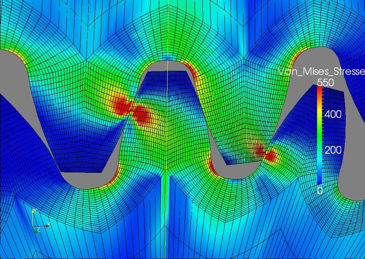
Based on what I see in the TR6060 design, the first gear has a margin of approximately 20%, i.e. even though the rated torque is 600 lb-ft, it should be possible to run 700 lb-ft through the gears themselves. For the remaining forward gear sets (2 through 6), the diameter of the drive gear gets larger, which means that the stresses in the gear drop dramatically. For the second gear at maximum torque, for the spur gear geometry the stress contours are shown below. The fillet root stress is only about 550 MPa, or 80 ksi. A good quality gear steel with the correct heat treatment can deal with this level of stress for a long long time. With appropriate modifications, the 2nd gear has a margin of well over 50 percent, i.e. a life of at least 2000 miles at 600 lb-ft engine torque. (Autocrossers rejoice! — JB)
For fifth and sixth gears, the design margin is usually well over 100 percent. The reason for this is the very high number of revolutions that these gear sets see under load. A 75,000 miles of durability in sixth gear with a 3.42 axle ratio and the usual range of tire sizes translates to 200 million stress cycles on the gear teeth. Therefore it is best to leave sufficient design margins for fifth gear and above.
Of course the TR6060 is often used in applications with only about 450 lb-ft of engine torque with this 2.97 first gear. In that case, the design life is much higher than the figures presented in this article. I would estimate that with a bone stock set up, the first gear will easily last 1200 miles or approximately 12000 WOT launches, the second gear is going to be good for at least 7000 miles, while other forward gears essentially have infinite life.
DISCLAIMER: I HAVE NOT looked at the bearings and the shafts, for these might very well be the weak link in the system, so if your transmission explodes @ 700 lb-ft of torque please do not hunt me down.
The purpose of this article is to provide the B&B with a glimpse of what goes into designing little parts that make up a whole car. Hopefully this article did meet the stated goals.
Acknowledgements: All the finite element analysis in this article has been carried out using a package called GGGears. This is a wonderful open source analysis package, though it is rough around the edges. The commercial equivalents cost a lot of money, GGGears does more than half of what the commercial packages do, and it costs nothing. More importantly, the source code is there for you to look at. Free as in freedom, and free as in beer.

More by Timur Apakidze


Comments
Join the conversation
Superbly written and highly informative article. Kudos to you, sir. Given the relatively low shelf life of the lower gears, it's little wonder "city miles" tend to age a vehicle so much sooner. When I worked in Chi-town (but lived in NW Indiana) I'd regularly log dozens of "expressway" miles every week barely crawling above second gear. Minimal engine load to be sure, but it still makes me wonder just how much harder these bumper-to-bumper miles can be on a car. What would be the "highway miles" equivalent of 50,000 stop-and-go miles be, in terms of wear and tear on the tranny? 100K? 150K?
I still don't understand why would not they just take a planetary set based transmission, then link the shift lever to oil valves. Put clutch instead of TQ, of course. Voila, torque capacity, no synchros.