


Original Documents: The Corvette Story (Circa 1961) by P.J. Passon
Okay, so it’s not The Christmas Story, but while trying to track down a since deleted summary of an upcoming Society of Automotive Engineers paper that leaked details of the 8 speed automatic transaxle that the 2015 Corvette will offer, I came across another SAE paper concerning the Corvette, this one published in 1961, titled The Corvette Story. In 1961, just 8 years after the first Corvettes went on sale, fiberglass bodied cars were still a new thing. Chevrolet engineer P.J. Passon’s paper for the SAE goes over the processes involved in making the Corvette bodies and then how the cars are assembled. He discusses the 1961 Corvette’s engineering features and explains why GM went with fiberglass instead of steel and also why mass-market Chevrolet was making and selling a sports car with limited market appeal. I’m sure that anyone with an interest in Corvettes and Corvette history will find it worthwhile, though it’s also a nice snapshot of advanced materials manufacturing circa 1961.
In its brief life span of eight years, the Corvette has undergone rapid character development. It has built up a clientele all its own – demanding, but enthusiastic. Their attitude is contagious, and progress has come fast. I do not intend to cover the history of the Corvette this morning, except to say that its roadability has increased since 1953 in roughly the same proportion as its power-to-weight ratio or approximately two-to-one.
Many interesting engineering concepts have been incorporated into this car, and I intend to cover them briefly this morning. However, since most of you people, and I hope all of you, are going to tour the Corvette assembly plant this afternoon, I want to tailor my talk to enable you to take full advantage of that opportunity. I’d like to answer the questions that would occur to you as you tour the plant; so in this comparatively quiet atmosphere I will give you a “Cook’s Tour,” concentrating on the interesting and unique operations that occur down the line.
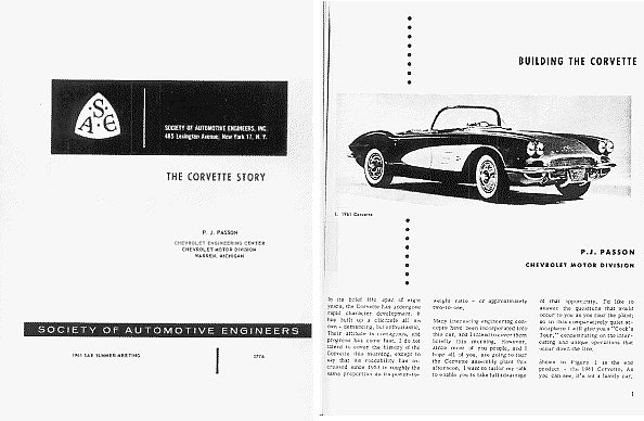
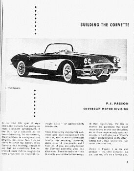
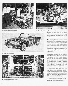
Shown in Figure 1 is the end product – the 1961 Corvette. As you can see, it’s not a family car.

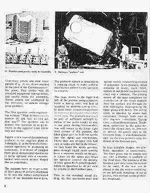
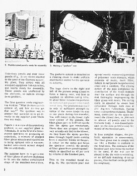
Underbody panels and door inner panels (Fig. 2) are shown stacked In the yard of the Corvette assembly plant. They arrive with all standard equipment holes punched, and nearly ready for assembly. These panels are unaffected by the elements, so outside storage is no problem.
The first question on the engineering mind is: “What do these panels consist of, and how do they get that way?” The quickest way to answer that question is to go directly to the supplier plant where they are made.
Figure 3 is a view of the underbody preform in our supplier plant in Ashtabula. It is the first of a three-station operation in producing an underbody. A mixture of chopped fiber glass strands and liquid resin is being sprayed onto a vacuum-backed wire-mesh screen shaped like an underbody.
The purpose here is to get a mat of fiber glass of uniform thickness to fit into the rather complicated shape of the matched-metal dies. The preform screen is mounted on a rotating drum to make uniform distribution easier for the operator to achieve.
The huge doors to the right and left of the picture swing closed to form a baking oven, and heat is supplied to shorten curing time. In about three minutes the preform is removed and placed in the match metal dies. The preform mat itself is only of sufficient strength by virtue of the resin binder to stay in one piece during this transfer. You will notice in the lower right hand corner of the picture, the fiber glass yarn is fed from spools into the spray gun mechanism. There they are chopped into half inch strands and fed to the blower. As they leave the spray gun they pass through liquid resin coming from a separate nozzle on the gun. A timer on the spray gun helps the operator control the density of fiber glass from panel to panel which is specified as 40 per cent by volume in the finished part.

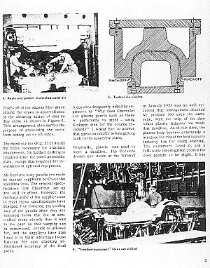
This is the matched metal die (Fig. 4). The operators pour and spread evenly measured quantities of polyester resin mixture, which consists of resin, inert filler, (which in our panels is a pulverized clay) and a catalyst. The closing action of the dies completes the distribution of the resin mixture over the surface and through the mat thoroughly impregnating the fiber glass with resin. The curing cycle is speeded by steam heat circulated through both dies at 250 degrees Fahrenheit. Curing time is about three minutes. Thick-ness, controlled by the space between the closed dies, is .100 inch in almost all panels used in the Corvette body. A wax-based lubricant on the dies permits easy removal of the finished part.
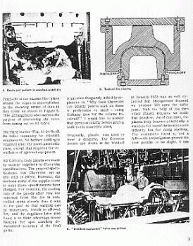
In less complex shapes, the pre-form operation is unnecessary. The fiber glass mat is simply laid out like a blanket to conform to the final dies. The contours of the finished part determine the method to be used. If the mat can be placed in the die with no wrinkling, or no difficult matching of cut up pieces, this method can be profitably employed. Pinch-off of the excess fiberglass around the edges is accomplished by the shearing action of dies as they close as shown in Figure 5. This arrangement also serves the purpose of preventing the resin from oozing out on all sides.
The third station (Fig. 6) drills all the holes necessary for standard attachments. No further drilling is required after the panel gets to the plant, except that required for installation of optional equipment.
All Corvette body panels are made by outside suppliers to Chevrolet specifications. The original specifications that Chevrolet set up are still in effect. However, the methods some of the suppliers use to meet these specifications have changed. For instance, the cooling rate of the panels after they are removed from the die is controlled more closely than it was in the past so that warping can be minimized. Shrink is allowed for, and the suppliers have also found it to their advantage to use fixtures for spot checking dimensional accuracy of the final parts. A question frequently asked by engineers is “Why does Chevrolet use plastic panels such as these in preference to steel – using Kirksite dies for the volume involved?” I would like to answer that question briefly before getting back to the assembly plant.
Originally, plastic was used to meet a deadline. The Corvette dream car shown at the Waldorf in January 1953 was so well received that Management decreed we produce 300 cars the same year. With the help of the then infant plastic industry we made that deadline. As of that time, the plastic body became practically a mandate for two of the best reasons industry has for doing anything. The customers loved it, and a full-scale investigation proved the cost penalty to be slight. It hasother advantages, of course. Probably its most significant property is its low weight.
The density of reinforced plastic, translated into comparable standards of required thickness, is still about half that of steel.
A square foot of plastic panel one tenth of an inch thick weighs half as much as the same size piece of standard .036 inch steel.
As you might expect, the use of fiber glass reduces the weight of the Corvette body by approximately 300 pounds – to little more than half the weight of a comparable steel body. This is, of course, a distinct advantage in maintaining a desirable power-to-weight ratio in a ear of this type. Fiberglass will not rust or corrode, and is impervious to any chemical substance to which it might be exposed in normal service. Our experience to date indicates that we can expect the first Corvette bodies to be around for a long time. In specifying the necessary physical properties of these panels, Chevrolet leaned heavily on its experience with sheet metal. In fact, we used what we called sheet metal-plastic equivalents.
The most fascinating investigation was covered very thoroughly by Mr. E. J. Premo at the SAE Annual Meeting in January 1954. This morning we only have time to recommend this paper entitled “The Corvette Plastic Body.” (Paper No. 212)
ASSEMBLY OPERATIONS
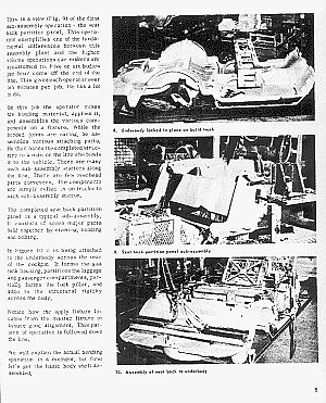
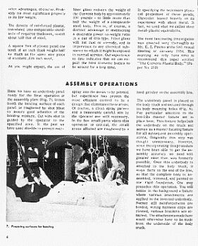
Here we have an underbody panel ready for the first operation at the assembly plant (Fig. 7). In this booth the bonding surface of each panel is roughened by shot blast to assure good adhesion of the bonding mixture. Cut wire shot is guided by the operator to the specified area. In the past we have used shields to prevent over-spray into the areas to be painted, but experience has proven the most efficient control to be a design that eliminates these areas. Of course, a clean spray pattern and a reasonably careful aim by the operator are still necessary. In the few small parts where this operation is critical, the small areas affected are roughened by a 7. Preparing surfaces for bonding hand grinder on the assembly line.
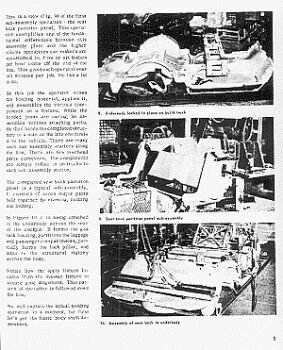
The underbody panel is placed on the body truck and secured through its body mounting holes (Fig. 8). Pay particular attention to the box-like master fixture set in place here. This fixture helps lock the underbody on the truck and serves as a master locating fixture for all subsequent assembly operations. Originally this step was thought unnecessary. However, since incorporating this procedure we have been able to get the assembly accuracy we need with greater ease than was formerly possible. Once this underbody is attached to the body truck, it stays there to the end of the line, so that the complete body is assembled, trimmed, and painted on one rigid foundation. One step precedes this operation. You will notice in the background a fixture where various attachments are applied to the inverted underbody. Rocker sill reinforcements are bonded, wiring harness clips are riveted, various brackets are attached. The attachments made here would otherwise have to be made from the underside of the body truck.This is a view (Fig. 9) of the first sub-assembly operation – the seat back partition panel. This operation exemplifies one of the fundamental differences between this assembly plant and the higher volume operations car makers are accustomed to. Five or six bodies per hour come off the end of the line. This gives each operator over ten minutes per job. He has a lot to do.
On this job the operator mixes his bonding material, applies it, and assembles the various components on a fixture. While the bonded joints are curing, he assembles various attaching parts. He then hands the completed structure to a man on the line who bonds it to the vehicle. There are many such sub-assembly stations along the line. There are few overhead parts conveyers. The components are simply rolled in on trucks to each sub-assembly station.
The completed seat back partition panel is a typical sub-assembly. It consists of seven major parts held together by riveting, bonding and bolting.
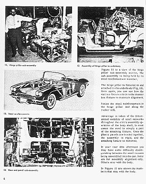
In Figure 10 it is being attached to the underbody across the rear of the cockpit. It forms the gas tank housing, partitions the luggage adds to the structural rigidity and passenger compartments, partially forms the lock pillar, and across the body. Notice how the apply fixture locates from the master fixture to assure good alignment. This pattern of operation is followed down the line. We will explain the actual bonding operation in a moment, but first let’s get the basic body shell assembled.Figure 11 is a view of the hinge pillar sub-assembly station. The sub-assembly is being held by its steel reinforcement member.
The hinge pillar is fixtured In and attached to the underbody (Fig. 12). Here again, you can see how the various fixtures tie into the master box fixture to maintain alignment.
Notice the steel reinforcement in the hinge pillar and along the rocker sill.
Advantage is taken of the dimensional stability of steel networks throughout the entire assembly operation of the body shell. In most cases the steel is simply a part of the attaching fixture. Once the plastic panels are bonded together, the assembly is rigid, and the attaching fixture is removed.
In your tour this afternoon you may have some difficulty distinguishing between the steel trusses being assembled into the car. Some are for assembly alignment only. Others stay with the body.
In Figure 13 are shown the members that stay with the body. Attachment of the reinforcements to the fiber glass is accomplished by means of aluminum rivets, or in some cases a bonding strip is riveted to the metal, and the main panel is bonded to the strip. In no case is fiber glass bonded to metal.
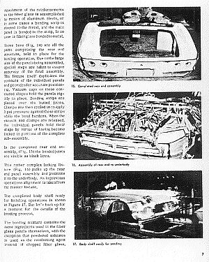
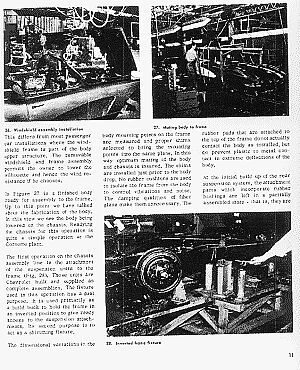
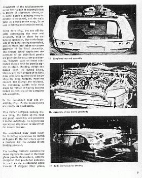
Shown here (Fig. 14) are all the parts comprising the rear end structure, held in place for the bonding operation. Due to the large size of the panels being assembled, special steps are taken to assure accuracy of the final assembly. The fixture itself duplicates the contours of the individual panels and provides for accurate positioning. Vacuum cups on these contoured shapes hold the panels rigidly in place. Bonding strips are placed over the butted joints. Clamps are then cycled in to apply 3 psi pressure against these strips while the bond hardens. When the vacuum and clamps are released, the individual panels hold their shape by virtue of having become locked in portions of the complete sub-assembly.
In the completed rear end assembly, (Fig. 15) the bonded joints are visible as black lines.
This rather complex looking fixture (Fig. 16) picks up the rear end panel assembly and positions it to the underbody. As in previous operations alignment is taken from the master fixture.
The completed body shell ready for finishing operations Is shown in Figure 17. But let’s back up for a moment for the details of the bonding process.
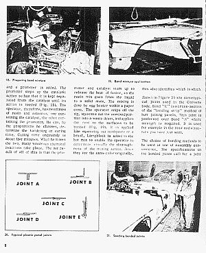
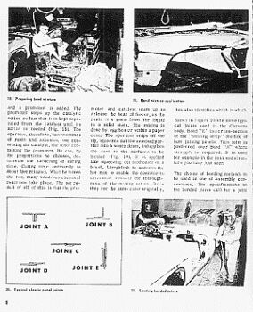
The bonding mixture contains the same ingredients used in the fiber glass panels themselves, with the exception that powdered asbestos is used as the reinforcing agent instead of chopped fiber glass, and a promoter is added. The promoter steps up the catalytic action so fast that it is kept separated from the catalyst until its action is needed (Fig. 18). The operator, therefore, has two mixes of resin and asbestos, one containing the catalyst, the other containing the promoter. He can, by the proportions he chooses, determine the hardening or curing time. Curing time ordinarily is about five minutes. When he mixes the two, many wondrous chemical reactions take place. The net result of all of this is that the promoter and catalyst team up to release the heat of fusion, as the resin mix goes from the liquid to a solid state. The mixing is done by egg beater within a paper cone. The operator snips off the tip, squeezes out the unmixed portion into a waste drum, and applies the rest to the surfaces to be bonded (Fig. 19). It is applied like squeezing out toothpaste on a brush. Lampblack is added to the hot mix to enable the operator to determine visually the thoroughness of the mixing action. Since they are the same color originally, this also identifies which is which.
Shown in Figure 20 are some typical joints used in the Corvette body. Bond “E” is a cross- section of the “bonding strip” method of butt joining panels. This joint is preferred over Bond “A” where strength is required. It is used for example in the rear end structure you have just seen.
The choice of bonding methods to be used is one of assembly convenience. The specifications on the bonded joints call for a joint that is as strong as the panels being joined. Tests indicate that the panels will fail before the joint. Approximately 20 quarts of bonding mix are used on each vehicle.
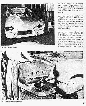
After the body is assembled, all bonded joints are sanded in one operation in the body finishing area (Fig. 21). The entire panels are also dry sanded to smooth surfaces. The operators have fresh air supplied into those hoods they are wearing.
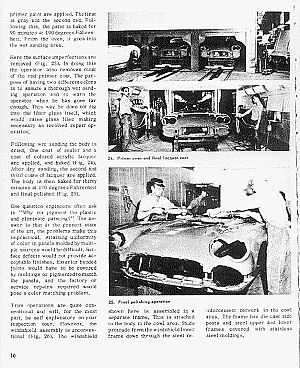
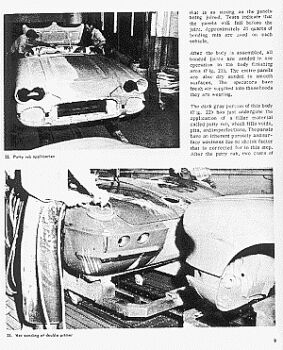
The dark gray portion of this body (Fig. 22) has just undergone the application of a filler material called putty rub, which fills voids, pits, and imperfections. The panels have an inherent porosity and surface waviness due to shrink factor that is corrected for in this step. After the putty rub, two coats of primer paint are applied. The first is gray and the second red. Following this, the paint is baked for 90 minutes at 190 degrees Fahrenheit. From the oven, it goes into the wet sanding area.
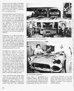
Here the surface imperfections are removed (Fig. 23). In doing this the operator also removes most of the red primer coat. The purpose of having two different colors is to assure a thorough wet sanding operation and to warn the operator when he has gone far enough. This way he does not dig into the fiber glass itself, which would raise glass fiber making necessary an involved repair operation.
Following wet sanding the body is dried. One coat of sealer and a coat of colored acrylic lacquer are applied, and baked (Fig. 24). After dry sanding, the second and third coats of lacquer are applied. The body is then baked for thirty minutes at 170 degrees Fahrenheit and final polished (Fig. 25).

One question engineers often ask is “Why not pigment the plastic and eliminate painting?” The answer is that at the present state of the art, the problems make this impractical. Attaining uniformity of color in panels molded by multiple sources would be difficult. Surface defects would not provide acceptable finishes. Exterior bonded Joints would have to be covered by moldings or pigmented to match the panels, and the factory or service repairs required would pose a color matching problem.
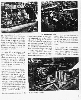
Trim operations are quite conventional and will, for the most part, be self explanatory on your inspection tour. However, the windshield assembly is unconventional (Fig. 26). The windshield shown here is assembled in a separate frame. This is attached to the body in the cowl area. Studs protrude from the windshield lower frame down through the steel reinforcement network in the cowl area. The frame has die cast side posts and steel upper and lower frames covered with stainless steel moldings. This differs from most passenger car installations where the windshield frame is part of the body upper structure. The removable windshield and frame assembly permits the owner to lower the silhouette and hence the wind resistance if he chooses.
In Figure 27 is a finished body ready for assembly to the frame. Up to this point we have talked about the fabrication of the body. In this view we see the body being lowered on the chassis. Readying the chassis for this operation is quite a simple operation at the Corvette plant.
The first operation on the chassis assembly line is the attachment of the suspension units to the frame (Fig. 28). These units are Chevrolet built and supplied as complete assemblies. The fixture used in this operation has a dual purpose. It is used primarily as a build buck to hold the frame in an inverted position to give ready access to the suspension attachments. Its second purpose Is to act as a shimming fixture.
The dimensional variations in the body mounting points on the frame are measured and proper shims selected to bring the mounting points into the same plane. In this way optimum mating of the body and chassis is insured. The shims are installed just prior to the body drop. No rubber cushions are used to isolate the frame from the body to control vibrations and noise. The damping qualities of fiberglass make them unnecessary. The rubber pads that are attached to the top of the frame do not actually contact the body as installed, but do prevent plastic to metal contact in extreme deflections of the body.
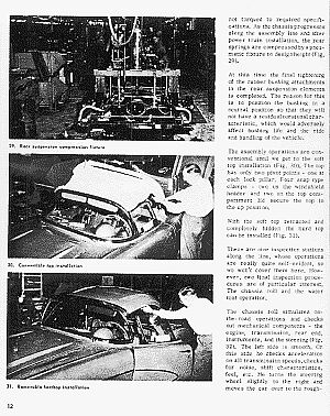
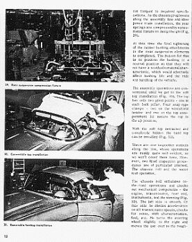
At the initial build up of the rear suspension system, the attachment parts which incorporate rubber bushings are left in a partially assembled state – that is, they are not torqued to required specifications. As the chassis progresses along the assembly line and after power train installation, the rear springs are compressed by pneumatic fixture to design height (Fig. 29).
At this time the final tightening of the rubber bushing attachments in the rear suspension elements is completed. The reason for this is to position the bushing in a neutral position so that they will not have a residual torsional characteristic, which would adversely affect bushing life and the ride and handling of the vehicle.
The assembly operations are conventional until we get to the soft top installation (Fig. 30). The top has only two pivot points – one at each lock pillar. Four snap type clamps – two on the windshield header and two on the top compartment lid secure the top in the up position.
With the soft top retracted and completely hidden the hard top can be installed (Fig. 31).
There are nine inspection stations along the line, whose operations are really quite self-evident, so we won’t cover them here. However, two final inspection procedures are of particular interest. The chassis roll and the water test operation.
The chassis roll simulates on-the-road operations and checks out mechanical components – the engine, transmission, rear end, instruments, and the steering (Fig. 32). The left side is smooth. On this side he checks acceleration on all transmission speeds, checks for noise, shift characteristics, feel, etc. He turns the steering wheel slightly to the right and moves the car over to the rough-road side of the rolls. This produces considerable vehicle shake, so that any miss-assembly will soon make itself known.
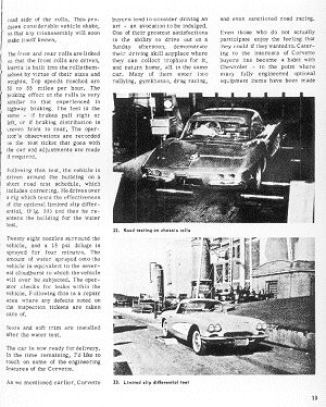
The front and rear rolls are linked so that the front rolls are driven. Inertia Is built into the rolls themselves by virtue of their sizes and weights. Top speeds reached are 50 to 55 miles per hour. The braking effect on the rolls is very similar to that experienced In highway braking. The feel is the same – if brakes pull right or left, or if braking distribution is uneven front to rear. The operator’s observations are recorded on the test ticket that goes with the car and adjustments are made if required.
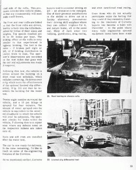
Following this test, the vehicle Is driven around the building on a short road test schedule, which includes cornering. He drives over a rig which tests the effectiveness of the optional limited slip differential, (Fig. 33) and then he re-enters the building for the water test.
Twenty eight nozzles surround the vehicle, and a 18 psi deluge is sprayed for four minutes. The amount of water sprayed onto the vehicle is equivalent to the severest cloudburst to which the vehicle will ever be subjected. The operator checks for leaks within the vehicle. Following this is a repair area where any defects noted on the inspection tickets are taken care of. Seats and soft trim are installed after the water test. The car is now ready for delivery. In the time remaining, I’d like to touch on some of the engineering features of the Corvette.
As we mentioned earlier, Corvette buyers tend to consider driving an art – an avocation to be indulged. One of their greatest satisfactions is the ability to drive out on a Sunday afternoon, demonstrate their driving skill anyplace where they can collect trophies for it, and return home, all in the same car. Many of them enter into rallying, gymkhanas, drag racing, and even sanctioned road racing.
Even those who do not actually participate enjoy the feeling that they could If they wanted to. Catering to the interests of Corvette buyers has become a habit with Chevrolet – to the point where many fully engineered optional equipment items have been made available to them. To name a few:
— 5 engines, headed by fuel injection — a fully synchronized 4-speed transmission — a quick steering option — a built-in fast clutch adjustment — and heavy duty suspension and brake options.
These interests have inspired many significant refinements. As an example:
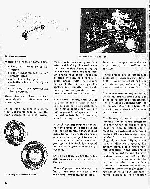
In the rear suspension system, (Fig. 34) radius rods relieve the rear springs of the axle housing torque reactions during acceleration and braking. Located above the front portion of the rear spring between the frame and rear axle, the radius rods control rear axle rotation by forming a parallelogram linkage with the forward halves of the leaf springs. The springs are virtually free of axle housing torque providing more consistent and precise handling.
A standard steering ratio of 21:1 is used on the production Corvettes. This ratio is satisfactory for normal sports car use and makes possible adequate cornering with relatively light steering wheel handling and effort.
A quick steering adapter is available to reduce the ratio to 16.3:1 for the fast intricate maneuvering many Corvette enthusiasts are required to do in competitive events. It comes as part of a heavy duty package which includes special brakes and higher rate shock absorbers.
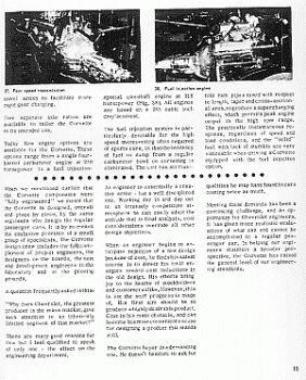
Shown in Figure 35 are the heavy duty brakes with sintered metallic linings. Physical properties of the metallic linings are such that high brake operating temperatures do not affect their composition and more significantly, their coefficient of friction.
These brakes are extremely fade resistant; incorporating finned brake drums, vented backing plates with air scoops, and cooling fins mounted inside the brake drums.
The brakes are virtually unaffected by water, and oil does not tend to deteriorate sintered iron linings. The air scoops supplied with the option are shown in Figure 36.
They are owner-installed for competitive events.
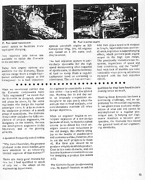
The Powerglide automatic transmission was standard equipment on early Corvettes and is offered today, but only as optional equipment on the two lowest horsepower engines, Of more interest perhaps, is the four speed transmission (Fig. 37) which is fully synchronized in all forward speeds. The closely stepped gear ratios permit operation in the high engine output range and the use of engine braking through down shifting. The four speed transmission is the only one on the market with a positive action reverse inhibitor. A further innovation in clutch linkage design makes possible either normal release action or shorter travel action to facilitate more rapid gear changing.
Five separate axle ratios are available to tailor the Corvette to its intended use.
Today five engine options are available for the Corvette. These options range from a single four barrel carburetor engine at 230 horsepower to a fuel injection special camshaft engine at 315 horsepower (Fig. 38). All engines are based on a 283 cubic inch displacement.
The fuel injection system is particularly desirable for the high speed maneuvering often required of sports cars, in that the tendency of fuel to dump from a regular carburetor bowl on cornering is eliminated. The unit has air manifold ram pipes tuned with respect to length, taper and cross-section-al area, to produce a supercharging effect, which permits peak engine output in the high rpm range. The practically instantaneous response, regardless of speed and load conditions, and the “solid” feel with lack of stumble are very noticeable when driving a Corvette equipped with the fuel injection option.
When we mentioned earlier that the Corvette components were “fully engineered” we meant that the Corvette is designed, overall and piece by piece, by the same engineers who design the regular passenger cars. It is by no means the exclusive province of a small group of specialists. The Corvette design crew includes the full complement of project engineers, the designers on the boards, the test and development engineers in the laboratory and at the proving grounds.
A question frequently asked is this:
“Why does Chevrolet, the greatest producer in the mass market, give such attention to an inherently limited segment of that market?”
There are many good reasons for this but I feel qualified to speak of only one – the effect on the engineering department. An engineer is essentially a creative artist – but a well disciplined one. Working day in and day out In an intensely competitive atmosphere he can easily adopt the attitude that in final analysis, cost considerations override all other design objectives.
When an engineer begins to anticipate rejection of a new design because of cost, he finds his safest course is to direct his total energies toward cost reductions in the old design. His efforts bring joy to the hearts of stockholders and customers alike. However, this is not the stuff progress is made of. His first aim should be to produce a highly desirable product. Cost is his main obstacle, and can become his most convenient excuse for designing a product that stands still.
The Corvette buyer is a demanding one. He doesn’t hesitate to ask for qualities he may have found in cars costing twice as much.
Meeting these demands has been a continuing challenge, and an opportunity for Chevrolet engineers. It has given more realistic evaluations of what can and cannot be accomplished in a regular passenger car. In helping our engineers maintain a broader perspective, the Corvette has raised the general level of our engineering standards.


Ronnie Schreiber edits Cars In Depth, the original 3D car site.
More by Ronnie Schreiber


Comments
Join the conversation
"The mixing is done by egg beater within a paper cone." My, how automotive assembly processes have changed.
This widened my eyes a bit: "The bonding mixture contains the same ingredients used in the fiber glass panels themselves, with the exception that powdered asbestos is used as the reinforcing agent instead of chopped fiber glass, and a promoter is added." And this (a few paragraphs later): "After the body is assembled, all bonded joints are sanded in one operation in the body finishing area (Fig. 21). The entire panels are also dry sanded to smooth surfaces. The operators have fresh air supplied into those hoods they are wearing." Whew. This is my favorite excerpt: "There are many good reasons for this but I feel qualified to speak of only one – the effect on the engineering department. An engineer is essentially a creative artist – but a well disciplined one. Working day in and day out In an intensely competitive atmosphere he can easily adopt the attitude that in final analysis, cost considerations override all other design objectives. When an engineer begins to anticipate rejection of a new design because of cost, he finds his safest course is to direct his total energies toward cost reductions in the old design. His efforts bring joy to the hearts of stockholders and customers alike. However, this is not the stuff progress is made of. His first aim should be to produce a highly desirable product. Cost is his main obstacle, and can become his most convenient excuse for designing a product that stands still." True Dat -- The problem with "cost containment" is that razor-thin margins lead to a less-robust design, which (more often than not) will result in marginal performance (or even outright failures) late in product development, which means either releasing a sub-standard product to meet the schedule, or going "back to the drawing board", thus missing the schedule, and possibly being beat by competitors. The best "insurance policy" is to overbuild your design, and if it performs well in actual use, take cost out in later iterations where there is room to do so.