


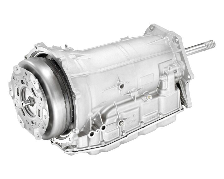
Saturation Dive: The GM 8L90 Transmission
On the surface, there are many similarities between the ZF 8HP transmission family and the GM 8L90. Namely both use 4 gear sets, 5 shifting elements (3 clutches and two brakes), off axis pumps, and have roughly the same gear ratio spread at about 7:1 overall spread. The saturation dive is not about dealing with things that are on the surface. To be entirely honest as the details started to emerge on the GM 8L family of transmissions I suspected that it would end up being a ZF licensed design, the ZF 8HP after all is a very good design in my opinion. But the abstract of the paper that we managed to snag before SAE took it down revealed one very important detail – all 3 of the clutches were located in front of the planetary gear sets very much unlike the ZF design.
The amount of information available publicly on the 8L90 is very sparse and is right now limited to the the SAE papers the engineers responsible for the transmission wrote and the patent granted to GM. The folks at SAE want money for the paper, but the patent is available as a matter of public record from the USPTO. The structure of this particular saturation dive is therefore going to be a bit different from the past ones. Please refer to the earlier saturation dives for a rehash of the basics of gears. The drawing from the patent filing is shown below
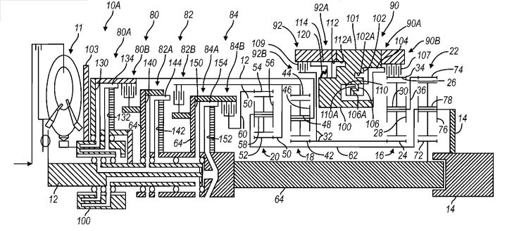
GM 8L90 patent drawing
The stick diagram
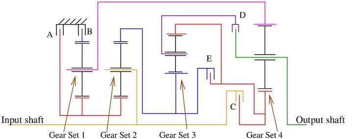
Since the patent diagram is not the easiest thing in the world to read, the stick diagram for the transmission is shown below. The output shaft of the torque converter is the input shaft for this gear arrangement.
Stick diagram for the GM 8L90
As we see from the stick diagram, there are 4 simple planetary gear sets. The shift elements function as follows
- Brake A when activated grounds the sun gears of gear sets 2 and 3
- Brake B activation grounds the ring gear of gear set 3
- Clutch C activation ties the input shaft to the sun gear of gear set 4
- Clutch D activation ties the ring gear of gear set 1 to the sun gear of gear set 4
- Clutch E activation ties the ring gear of gear set 2 and the syn gear of gear set 1 to the sun gear of gear set
Additionally, the following rigid links exist
- The input shaft is rigidly connected the planetary carrier of gear set 2
- The sun gear of gear set 1 and the ring gear of gear set 2 are connected together
- The sun gears of gear sets 2 and 3 are connected together
- The planetary carriers of gear sets 1 and 4 are tied together – which in turn is the output shaft of the transmission
- The planetary carrier of gear set 3 is tied to the ring gear of gear set 4
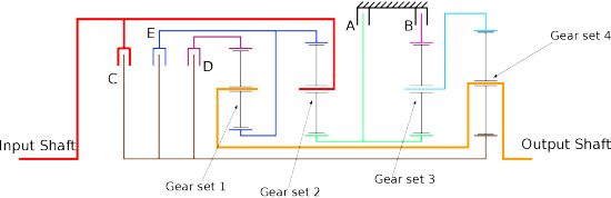
Clearly while there are similarities, the planetary gear arrangements for the ZF 8HP and the GM 8L90 are actually quite distinct in layout. The stick diagram for the ZF 8HP is shown below.
Stick diagram for the ZF 8HP
The similarities between the 2 layouts are enumerated as follows
- Rigid links between 2 sun gears, but between gear sets 2 and 3 for the GM design vs. gear sets 1 and 2 for the ZF design
- Rigid link between planetary carrier of a gear set and the ring gear of gear set 4, but between gear sets 3 and 4 for the GM design vs. gear sets 1 and 4 for the ZF design
- Rigid link between the input shaft and the planetary carrier of gear set 2
The major difference is that the ZF 8HP uses two rigid links between the sun gears and ring gears of adjacent gear sets, the 8L90 uses one such link and has a separate rigid link between the planetary carriers of gear sets 1 and 4. Therefore the GM 8L90 is a unique layout that is different from the ZF 8HP but there are similarities that are quite obvious as well.
First gear
The first gear is achieved by engaging both brakes A and B and clutch C. Engagement of brakes A and B locks the sun gear and the ring gear of gear set 3 to ground, which means that the planetary carrier of gear set 3 is tied to ground as well. Since this planetary carrier is rigidly tied to the ring gear of gear set 4, this means that the ring gear of gear set 4 is stationary. The engagement of clutch C ties the input shaft to the sun gear of gear set 4. This sets up an underdrive gear with a ratio of
(1)1st =S4+R4S4
= 4.5517We know that the gear ratio is around 4.55, and also that given the torque capacity requirements GM is more than likely using 4 pinions for higher torque rating similar to the ZF design, therefore (S4+R4) has to be divisible by 4. Also (R4-S4) has to be an even number. A candidate tooth count is S4=29 and R4=103, which leads to a feasible arrangement with 4 37 tooth planetary pinions and a first gear ratio of 4.5517, which is quite close to the known ratio. Since S4+R4 = 132 is divisible both by 4 and 3, for the lighter duty versions of the 8L family it is possible for GM to reduce the number of planetary pinions to 3 for applications that don’t quite require the 1000 Nm the 8L90 is capable of.
For the first gear operation, the GM 8L90 and ZF 8HP are therefore kinematic equivalents, but there is one very significant difference, the GM design places the brakes right next to the output gear set. The reason it matters is because at full torque (1000 Nm) and a 4.55 gear ratio, the 2 brakes are reacting a total of 3550 Nm of torque. The reaction torque in the ZF design has to pass through the outermost tube to the front of the transmission, i.e. approximately a 1.5 kg shaft assuming that the wall thickness is 3 mm, the length is approximately 350 mm and the inner diameter is around 180 mm. Now 1.5 kg does not sound like a lot, the problem is it is at a very large diameter, and rotational inertia is proportional to the square of the diameter. The rotating inertia of the ZF shaft is approximately 0.01 kg-m^2 while the GM design is around a tenth of that because it is at a much smaller diameter.
The input shaft in case of the GM design ends up being the outermost shaft, but the input shaft only carries engine torque while the outermost shaft in case of the ZF design has to carry 3.7 times the engine torque. Also, it appears that the length of the outer shaft in case of the GM design will be shorter than the ZF design.
The lower inertia of the GM design will shave a few precious milliseconds off the shift time, and in a world where the burgerkingring times are important, over a course of a lap the precious milliseconds can add up to a second. As the B&B we all know just how important the burgerkingring times are to market share. On a more serious note, this reduced inertia will also show up as a very small fraction of a mile per gallon for the EPA fuel economy.
Second gear
To shift up to second gear, both brakes A and B stay locked, clutch C is disengaged and E is engaged. Doing so connects the sun gear of gear set 4 to the ring gear of gear set 2. The sun gear of gear set 1 is grounded and the planetary carrier of gear set 2 is connected to the input. Therefore this sets up an overdrive cascaded with an underdrive. The ratio is
(2)2nd =(S4+R4)R2S4(R2+S2)
= 2.9586Knowing the gear ratio, and methods similar to the 1st gear estimation, a feasible and perhaps reasonable estimates for tooth counts is S2=42, R2=78 with an 18 tooth planetary pinion. Since S2+R2 = 120, it is possible to put in 3 or 4 pinions. Once again, the second gear operation is kinematically equivalent to the ZF 8HP. The earlier observations about overall transmission inertia being lower for the GM 8L90 still stand.
Third gear
The shift up to third gear is accomplished by releasing brake A, and engaging clutch E. Therefore shift elements B, C, and E are engaged. By doing so, the ring gear and the planetary carrier of gear set 2 turn at the same speed as the input, and therefore the sun gear of gear set 2 also turns at the input speed. Since this sun gear is linked to the sun gear of gear set 3, and the ring gear of gear set 3 is grounded by brake B, the carrier of gear set 3 is under driven with respect to the input. Therefore gear set 4 acts as a mixer module, with the sun gear rotating at the input speed, the ring gear turning slower than the input, forcing the carrier to turn at a speed that is slower than the input. The ratio is
(3)3rd =(S3+R3)(S4+R4)S4R3+S3S4+S3R4
= 2.0745Knowing the gear ratio, and methods similar to the 1st gear estimation, a feasible and perhaps reasonable estimates for tooth counts is S3=39, R3=77 with an 19 tooth planetary pinion. Since S3+R4 = 116, it is possible to put in 4 pinions. The operation of third gear is somewhat similar to the third gear of the ZF 8HP, this design uses gear sets 2, 3, and 4 while the ZF design uses gear sets 1, 2, and 4. Gear set 4 acts as a mixer module in both cases.
Fourth gear
The 4th gear up shift is achieved by releasing clutch C and engaging clutch D, i.e. shift elements B, D, and E are engaged. Engaging B and D at the same time means that the ring gear and sun gear of gear set 1 spin together with the sun gear of gear set 4. Since the planetary carriers of gear set 1 and 4 are linked together, all 3 members of gear sets 1 and 4 spin together at the output speed along with the ring gear of gear set 2 and the planetary carrier of gear set 3. Since the ring gear of gear set 3 is grounded, this causes the sun gears of gear sets 2 and 3 to be overdriven with respect to the output by a factor of approximately 3. This causes gear set 2 to act as a mixer module, with the planetary carrier as the input and sets up an underdrive gear. The ratio is
(4)4th =1 +S2R3S3(R2+S2)
= 1.6910The fourth gear power flow is significantly different from the ZF 8HP fourth gear power flow.
Fifth gear
Fifth gear is achieved by releasing clutch E and engaging clutch C, i.e. shift elements B, C, and D are engaged. The fifth gear power flow is quite challenging to understand, but I am going to give it the old college try. Since C and D are engaged, the following members turn at the input speed
- The ring gear of gear set 1
- The planetary carrier of gear set 2
- The sun gear of gear set 4
The planetary carriers for gear sets 1 and 4 are rigidly linked together and turn at the output speed. Ring gear of gear set 3 is grounded because brake B is engaged. This sets up the following kinematic states
- The sun gears of gear sets 2 and 3 are rotating at 2.16 times the input speed
- Since the ring gear of gear set 3 is grounded, the planetary carrier of gear set 3 is therefore spinning at 0.73 times the input speed
- Since the ring gear of gear set 4 is connected to the planetary carrier of gear set 3, gear set 4 becomes a mixer module with the sun gear spinning at input speed, the ring gear spinning at 0.73 times the input speed, and the planetary carrier being the output.
The 5th gear ratio is therefore
(5)5th =S1S3(R2+S2)(R4+S4) + S3R2(R4R1-S4S1) + R3S2S1(S4+R4)S1S3(R2+S2)(R4+S4) + S3R2(R4R1x-S4S1) + R3S2S1S4
= 1.2682Knowing the gear ratios, it is possible to back calculate a feasible gear parameters for gear set 1. After a little bit of work, S1 = 39, and R1 = 77 with 19 teeth planetary pinions. Therefore gear sets 1 and 3 appear to be identical in terms of number of gear teeth.
The kinematic state of gear set 4 is very much the same as the kinematic state for gear set 4 of the ZF 8HP, but the way the kinematic state is achieved is different. All 4 gear sets are used to achieve this ratio, albeit in a different manner than the ZF design.
Sixth gear
Sixth gear is achieved by releasing brake B and engaging clutch E, i.e. the 3 rotating clutches C, D, and E are all engaged but both brakes A and B are open. This means all members of all 4 gear sets turn at the same speed as the input. The ratio is therefore quite simply
(6)6th = 1.0000Seventh gear
Up shift to seventh gear is accomplished by releasing clutch E and engaging brake A. The engagement of brake A grounds the sun gear of gear set 2, while the engagement of clutches C and D connects the ring gear of gear set 1 to the input shaft. The ring gear of gear set 2 spins approximately 1.5 times faster than the input because the sun gear is grounded, the planetary carrier is the input, and the ring gear is the output. Therefore gear set 1 acts like a mixer module, with the sun gear rotating at approximately 1.5 times the input speed (due to the rigid connection to the ring gear of gear set 1), the ring gear turning at the input speed, and the planetary carrier being the output. The ratio is therefore decided by the ratios of gears sets 1 and 2 alone
(7)7th =R2(S1+R1)R2(S1+R1)+S1S2
= 0.8467Eight gear
Eight gear is achieved by disengaging clutch C and engaging clutch E, i.e. shift elements A, D, and E are engaged. Engaging clutches E and D at the same time causes all 3 members of gear set 1 to rotate at the same speed, and since the planetary carrier of gear set 1 is also the output shaft, this means that the ratio is decided strictly by the gear teeth count of gear set 2. The sun gear of gear set 2 is grounded, the planetary carrier is the input and the ring gear is the output. The ratio is therefore
(8)8th =R2R2+S2
= 0.6500Reverse gear
Reverse gear is achieved by locking both brakes A and B, and engaging clutch D. The sun gear of gears set 2 and the ring gear of gear set 4 are therefore grounded, the sun gear of gear set 1 spins at approximately 1.5 times the input speed (just as it does in 7th and 8th gears). The kinematic constraints imposed by the rigid link between the planetary carriers of gear sets 1 and 4, along with the actuation of clutch D which locks the ring gear of gear set 1 with the sun gear of gear set 4 causes the sun gear of gear set 4 to spin backwards at approximately 1.17 times the input speed, which means that the transmission output spins backwards but 3.908 times slower than the output
(Rev)Reverse =R2(S1S4-R1R4)S1S4(S2+R2)
= -3.9080What have we learned
Based on the available information, this article makes educated guesses at likely gear parameters for the GM 8L90. The likely gear parameters are
- Gear set 1: Sun gear S1 = 39, Ring gear R1 = 77
- Gear set 2: Sun gear S2 = 42, Ring gear R2 = 78
- Gear set 3: Sun gear S3 = 39, Ring gear R3 = 77
- Gear set 4: Sun gear S4 = 29, Ring gear R4 = 103
The gear ratio spacing is very good, the transmission feel of the GM 8L90 should be very competitive to the acclaimed ZF 8HP family of transmissions.
There are some obvious similarities between the gear arrangement of the GM 8L90 and the ZF 8HP but there are significant differences as well. These similarities and differences have been explained in this article. The one advantage of locating the clutches close to the hydraulic pump and the valve body is better shifting times since less fluid has to be moved in and out of the clutch pistons to apply and release the clutches. Also, this design is likely very competitive in terms of mass for a given torque capacity, and is better than the ZF 8HP design in terms of rotational inertia.
There are other advances made in this transmission design as well, especially with regards to the hydraulic pump design. This particular transmission features a “cylinder deactivation” of sorts for the pump, when line pressure demands are low (highway cruising) half of the pump can be shut down to achieve higher efficiency while still retaining the pump displacement required to deliver enough flow rate for fast shifts.
Conclusions
This is a very good design, hats off to the engineers at GM. The filing date on the patent is May 1, 2009 therefore props to the management at GM for letting this program move forward through the darkest days of their bankruptcy. This will be considered a seminal design in the history of automatic transmissions.
More by Timur Apakidze


Comments
Join the conversation
Great article but the GM 8L90 is not that much different from the ZF 8HP. The powerflow in each gear of the GM 8L90 is the same as in the ZF 8HP. GM took the ZF 8HP and swapped the position of the Gearsets 1 and 3. They also changed the position of clutch D. But both changes have no effect on the powerflow in each gear. If you look at the big equation in this article for the GM 8L90 5th gear and change all the 1 into a 3 and all the 3 into a 1 you will have the same equation as for the 5th gear in your article about the ZF 8HP. You can also do this for all the other gears with the same result. Offcourse the clutches applied in each gear are for both transmissions also the same.
@Timur, Thanks for your write up and the effort involved. You've done a great job in describing technical issues in layman terms. You should write some reference material for technicians and technical reports for managers. They'd love this stuff.