Ur-Turn: Saturation Dive Into The ZF 9-Speed
A TTAC reader is an engineer with a major powertrain company, and offered his extremely detailed analysis of the ZF 9-speed. Consider this an AP level course in powertrain engineering.
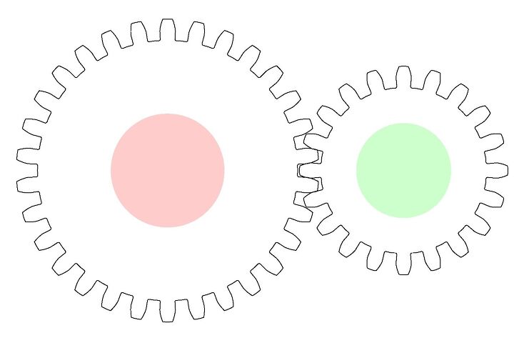
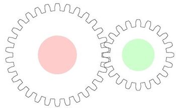
Before we dive right in to the 9-speed gearbox, let’s take a quick refresher on the basics of gears. The simplest gear set consists of 2 parallel gears mounted on 2 parallel shafts. Shown in Fig. is a gear set with a 20 tooth drive gear on the right and a 30 tooth driven gear on the left. For this gear set the speed of the driven gear is 1.5 times lower than the drive gear, and assuming no frictional losses anywhere, the torque on the driven gear is 1.5 times higher. This gear set has a ratio of 1.5:1. This type of a gear set is usually not favorable for packaging since it requires 2 parallel shafts, and there are largest separating forces that push the 2 gears apart which means that the bearings supporting the shafts have significant radial loads on them, in addition to an axial load if the gears are helical.
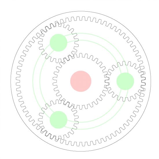
A simple planetary arrangement is shown in Fig. – this is the basis of most modern automatic transmissions. A simple planetary gear set has 3 members mounted on concentric shafts, the innermost gear is called a sun gear, the outermost gear is called the ring gear, and there are evenly spaced planetary pinions that mesh with both the sun gear and the ring gear. These pinions are free to spin around their own axes, and ride on the planetary carrier, which is the third concentric member. The radial forces in a planetary gear arrangement cancel out due to symmetry, and therefore the bearings supporting these shafts do not see much, if any radial loads. Since the 3 shafts are concentric, there are significant packaging advantages as well. This particular planetary arrangement has a 30 tooth sun gear, 72 tooth ring gear, and 21 tooth pinions. For this gear arrangement to go together, the difference between the number of teeth on the ring gear and the number of teeth on the sun gear has to be an even number, and the sum of teeth on the ring gear and the sun gear has to be divisible by the number of planetary pinions. In this case, the sum of the number of teeth on the ring gear and the sun gear is 102, which is divisible by the number of planets (3), hence this is a feasible gear arrangement.
Since there are 3 members in a planetary gear set, one member has to be grounded (i.e. forced to stand still) for there to be a ratio. There are 3 possible ground members (the sun gear, the ring gear, or the carrier), and 2 possible input and output combinations possible for each ground member, therefore this arrangement can provide 6 different speeds. If the number of teeth on the ring gear is denoted by R and the number of teeth on the sun gear is denoted by S
- If the ring gear is grounded by the use of a brake, the sun gear is the input and the carrier is the output, the
ratio of this arrangement is S+R/S or 3.4, i.e. the carrier is rotating 3.4 times slower
than the sun gear. Therefore in this configuration output is underdriven with respect to the input. If the carrier is
the input, and the sun gear is the output, then the output is overdriven by the same ratio. - If the sun gear is grounded, the ring gear is the input and the carrier is the output, the
ratio of this arrangement is S+R/R or 1.417, i.e. the carrier is rotating 1.417 times
slower than the ring gear. If the carrier is
the input, and the ring gear is the output, then the output is overdriven by the same ratio. - If the planetary carrier is grounded, the sun gear is the input and the ring gear is the
output, the ratio of this arrangement is R/S or -2.1875, i.e. the ring gear is rotating
2.1875 times slower than the sun gear and in the opposite direction. Therefore this arrangement
provides a reverse underdrive gear. If the ring gear is the input and the sun gear is the output,
this arrangement becomes a reverse overdrive, and who needs a reverse overdrive?
If 2 of the members are tied together, then the ratio of planetary becomes 1:1, as all members turn at the same speed. A single planetary gear with the right set of clutches and brakes to change the ground member, the input, and the output can provide 5 forward ratios and 2 reverse ratios with 9 shifting elements (6 clutches and 3 brakes). Of course it is not be possible to package the all 9 of the shifting
Planetary gears can also carry a lot more torque in the same packaging envelope because the load is distributed between multiple gear meshes. Need more torque capacity than the 3 planet gears can provide? You can nearly double that by putting in 6 planets on the planetary carrier.
Now on to the ZF 9 speed – there is a high level presentation available from the ZF website. This presentation has some detailed CAD renders in it, but not a whole lot of detail on the exact function of the transmission. The 2 CAD renders are shown tell us that there are 4 planetary gear sets in this transmission.
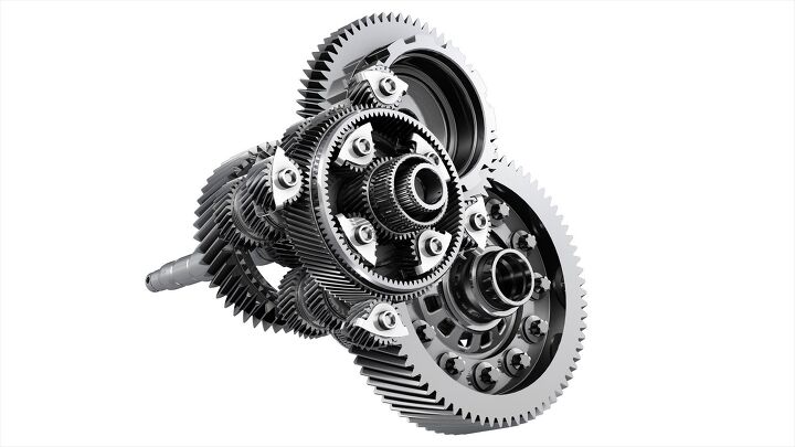
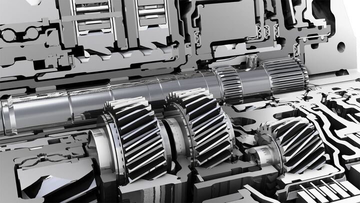
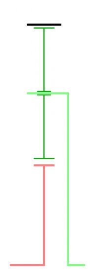
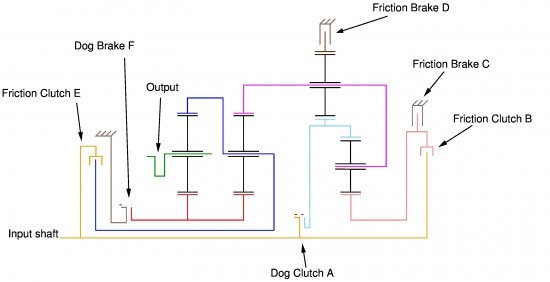
From these CAD renders the patient among the B&B can see that the one ring gear visible in Fig. has 86 teeth, and the 4 planets have 22 teeth, which means the sun gear that is not fully visible in the view is a 42 tooth gear. Fig. shows the stick diagram representation of the ZF 9 speed transmission, with 4 planetary gear sets numbered 1 through 4 from left to right. If one were to spend 10 minutes gawking at the cut-away transmissions that ZF does bring to trade shows, the following gear specifications can be established quite easily
- Gear set 1 has a 42 tooth sun gear and a 110 tooth ring gear
- Gear set 2 has a 42 tooth sun gear and a 110 tooth ring gear
- Gear set 3 has a 91 tooth sun gear and a 133 tooth ring gear
- Gear set 4 has a 42 tooth sun gear and a 86 tooth ring gear
The input is the output shaft of the torque converter, which is not shown in Fig.. The torque converter is obviously driven by the engine. The planetary carrier of gear set 1 is the output to the final drive of the transmission. The following elements are rigidly linked
- The 2 sun gears for gear sets 1 and 2 are connected together, in fact it is one wide gear
- The ring gear for gear set 1 is linked to the planetary carrier of gear set 2.
- The ring gear for gear set 2 is connected to the planetary carrier for gear set 3, which is also the
planetary carrier for gear set 4 - The sun gear for gear set 3 is linked to the sun gear of gear set 4
Additionally, the 6 shifting elements work as follows
- Dog clutch A in connected state connects the sun gear of gear set 3 and the ring gear of gear set 4 to the
input shaft - Friction clutch B couples the sun gear of gear set 4 to the input shaft
- Friction brake C ties the sun gear of gear set 4 to ground, i.e. stops it from turning
- Friction brake D ties the ring gear of gear set 3 to ground
- Friction clutch E couples the planetary carrier of gear set 2 and the ring gear of gear set 1
to the input shaft - Dog brake F ties the sun gears of gear sets 1 and 2 to the ground
Now on to the gory calculations
First gearFirst gear is achieved by engaging shift elements A, F, and D. In this configuration gear sets 1, 2, and 3 are used in series as underdrives, gear set 4 is just along for the ride. The sun gear of gear set 3 is connected to the input, and the ring gear is grounded, which leads to the carrier going slower than the input. The carrier is in turn connected to the ring gear of gear set 2, while the sun gear for gear set 2 is
An upshift to second gear is achieved by turning friction brake D off and engaging friction brake C, i.e. shift elements A, F, and C are engaged. Now gears sets 1, 2, and 4 are used as a cascaded series of underdrives. Operation of gears sets 1 and 2 is identical to the first gear, gear set 4 acts as an underdrive, while gear set 3 is along for the ride now. Gear set 4 acts as an underdrive because the transmission input is connected to the ring gear, the sun gear is held stationary by brake C, and the planetary carrier is the output. This leads to a ratio of
2ndgear=S4+R4R4S2+R2R2S1+R1R1=12886152110152110=2.8419The upshift to third hear is accomplished by releasing brake C and engaging clutch B. This operation causes both the ring gear and the sun gear of gear set 4 to be connected to the input, therefore the planetary carrier also turns at the same speed as the input. Since the planetary carrier of gear set 4 is connected to the ring gear of gear set 2, they both turn at the same speed, i.e. the input speed. The operation of gear sets 1 and 2 is unchanged, and they act as cascaded underdrives, yielding a gear ratio of
3rdgear=S2+R2R2S1+R1R1=152110152110=1.9094By releasing clutch B and engaging clutch E, the transmission up shifts to 4th gear, i.e. shift elements A, F, and E are engaged. This action connects the ring gear of gear set 1 to the input, while the sun gear is connected to ground, setting up a straightforward underdrive ratio of
3rd=S1+R1R1=152110=1.3818At this point, the 4 gear ratios have been achieved by leaving the 2 dog” elements engaged, and
To achieve fifth gear, dog brake F needs to be disengaged. This now leads to a brief torque interruption because as brake F is disengaged, the transmission is in Neutral and engaging the frictional element B prematurely would just lead to wear and tear on the transmission for no reason. At this point the transmission ECU and engine ECU are working in tandem to get this upshift done as quickly as possible. The ratio calculation is fairly trivial though, all 4 gear sets are turning at the speed of the input. Why? Because engaging elements A, B, and E means that
- The ring gear and the sun gear of gear set 4 are connected to the input, i.e. the planetary carrier
spins at the same speed as the input - Consequently, the sun gear and the planetary carrier for gear set 3 are spinning at the same
speed as the input, i.e. the ring gear gears for gear sets 2 and 3 are turning at the same speed as
the input - Through shift element E, the carrier of gear set 2 is turning at the same speed as the input,
therefore the sun gear of gear set 2 (which is also the sun gear for gear set 1) is spinning at
input speed - Since the ring gear and the sun gear of gear set 1 is turning at the same speed as the input,
the planetary carrier which is the transmission output is turning at input speed
The ratio therefore is quite simply
5th=1.000So far, things have been pretty simple but now the magic begins where planetary gear sets are going to act as mixer” modules, i.e. the input and output turn at different speeds, but the reacting or grounding member is also turning at some speed. The upshift to sixth gear is achieved by releasing clutch B and engaging brake C. This causes gear set 4 to act as an underdrive just like second gear, therefore ring gear of gear set 2 is turning at a speed which is approximately 1.5 times slower than the input speed. The difference between second gear and sixth gear is that brake F is disengaged andclutch E is engaged, which means that the common sun gear for gear sets 1 and 2 is spinning at approximately 1.85 times faster than the input. This sets up a kinematic state for gear set 1 where the ring gear is turning at the same speed as the input but the sun gear is turning at 1.85 times the speed of the input, therefore the carrier has to spin at approximately 1.25 times faster than the input speed – overdrive!. Since the B&B do not deal in approximations, the exact ratio is
6th=11+S4S4+R4R2S2S1R1+S1=0.8081As sixth gear shows us, an underdriven ring gear of gear set 2 sets up an overdrive, seventh gear kicks it up a notch by underdriving the ring gear of gear set 2 even further. This is accomplished by releasing brake C and engaging brake D. The sun gear of gear set 3 through clutch A is connected to the input, while the ring gear is connected to the ground via brake D, which means that the carrier spins 2.46
Eighth gear is achieved by closing brakes C and D at the same time, while disconnecting clutch A. At this point in time, the torque levels are low enough that in my humble opinion only the most discerning driver would be able to feel the torque interruption. This causes gear sets 3 and 4 to stop turning entirely, therefore the ring gear of gear set 2 is grounded. This causes the sun gear for gear sets 1 and 2 to spin faster – 3.65 times the input speed and sets up another over drive ratio
8th=11+R3S3+R3R2S2S1R1+S1=0.5802Therefore at 2000 rpm engine the sun gear for gear sets 1 and 2 is turning at 7300 rpm. But we are
If underdriving the ring gear of gear set 2 set up 2 overdrives, and grounding it set up another one, there is only one thing left to do, spin it backwards. Ninth gear does exactly that – by connecting clutch B and by the virtue of the fact that the ring gear for gear set 4 and the sun gear for gear set 3 are linked together, we have a very interesting kinematic state. Sun gear of gear set 4 spins at the input speed, the carrier for gear set 4 spins backwards at approximately half the input speed, and the ring gear turns backwards at 1.2 times the input speed. This means that the ring gear for gear set 2 is now spinning backwards at approximately half the input speed. The sun
The interesting thing about the Ninth gear is that there are parts in the transmission spinning
Reverse and 9th have the same kinematic states for gear sets 3 and 4, i.e. the ring gear for gear set 2 turns backwards at approximately half in the input speed. But gear sets 1 and 2 are switched over to an underdrive configuration which is identical to the configuration in First gear, i.e. brake F is engaged. The ratio is therefore
Rev=S4S3R4R3S4S3S2+R2R2S1+R1R1=3.8049The only real kink when shifting up through the gears is that the 4 to 5 shift might have an objectionable torque interruption, but otherwise this transmission is going to be well behaved. Downshifting from say 7th to 5th is no problem as well, but a downshift from 8th or 9th to 5th is hard work for this design. As an example if the engine speed is 1700 rpm and a shift from 8th to 5th
From eighth gear to fourth gear is going to be even more of a contortion, with a torque interruption that is about a second long as the transmission ECU and the engine ECU do this delicate dance required to get both the dog shifting elements to engage. When you are looking to pass on a 2 lane road at 60 mph, a second can feel like an eternity, especially to a driver who has to use those paddle shifters to get into the right gear before executing the pass.
Gear spacingAnother issue that the reviewers (including our own Alex L. Dykes) tend to take note of is the wide spacing between first and second gears. Unfortunately this is a direct result of the transmission lay out. Gear set 3 is pushed to the limit with the ratio, trying to make first gear ratio any lower than 4.7 would make the planetary gear pinion speed unreasonably high. So the first gear ratio is more or less
So a 50 tooth sun gets better spacing between first and second, somewhat worse spacing between second and third, all other gears are largely unchanged, expect that reverse gets screwed up – it is perhaps not low enough for vehicles with off road ambitions. So perhaps a happier middle ground could have been a 46 tooth sun of gear set 4, that leads to a reverse of 3.308 with a second gear ratio of
I give a Colbert Tip of the Hat” to the engineers at ZF for this design. It is obviously a clever design but one that could cause some drivability surprises to an average driver, though durability-wise, I see nothing that causes major concerns. Design and development of a transmission concept like this ranges from 20 million dollars
More by Ur-Turn


Comments
Join the conversation
HI can anyone please explain me how in sixth gear sun gear in set 1 and set 2 is said to rotate 1.85 times the input speed, I am new to automatic transmission trying to figure out the 9 speed gear ratio calculation if somebody give a quick reply it would be immensely helpful thanks....
Can somebody explain the calculation of 9th gear Gear ratio.I could not figure out how the speed of carrier of gear set 4 is rotating backwards at approximately half the input speed. Can anyone give a quick reply it would be immensely helpful.